By Marvin Drake, Spence Wise, Narasimha Charan and Ramraj Venkatadri
The current need for water footprint improvements and continuous cost reductions has made the reuse of process and wastewater in power plants increasingly important. This recycling of water will continue to be a significant topic as the industry moves into the future.
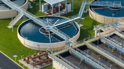
Cooling towers require the most water in power plants, accounting for about 90% of the plant's total water needs. A significant quantity of blowdown water is generated when running the cooling towers at different cycles of concentration, usually exceeding 4. In the past few years, the normal treatment scheme has the blowdown water being treated by softening and Reverse Osmosis (RO) membranes to remove suspended and dissolved contaminants. The treated blowdown water (permeate or filtrate) is then reused as boiler feed or process water. A portion of the blowdown, the RO reject stream, is sent to brine concentrators or evaporators. This is critical to enable the concept of zero liquid discharge (ZLD).
The treatment of blowdown water from the cooling towers is an enormous technical challenge and new technologies such as microfiltration (MF) as protection to RO treatment are increasingly being employed to meet the stringent specifications.

Inside Indiantown
The Indiantown, FL, Cogeneration plant is a 360 MW coal fired power plant. It has 2600 psi boilers supplying steam continuously to a "steam host." The cooling tower is run at 4-7 cycles of concentration. The plant is designated as a ZLD facility. Blowdown volumes treated from the cooling tower were designed to be 650 gpm. A Spray Drier Absorber (SDA) is used to reduce SOx emissions and evaporate the reject stream. Two brine concentrators were originally used to process cooling tower blowdown water and provide high-purity boiler feed water.
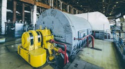
Brine Concentrators
Filtered makeup water is sent as feed to the cooling tower. Blowdown from the cooling tower was originally sent to the two brine concentrators (without membrane treatment), and the clean distillate from the brine concentrators was used as boiler feed water after mixed bed demineralizer treatment. The reject from the brine concentrators was used as feed water to the SDA and was evaporated by the heat from the fuel gas, thus achieving the desired zero liquid discharge. However, the brine concentrators suffered from extensive corrosion problems, requiring costly replacement.

The make up water to the cooling tower comes from three different sources:
1. Surface water from Taylor Creek, which is high in organics and cannot be used during droughts. This is the primary water supply for the plant.
2. Highly saline ground water from wells. This is used only during droughts and creates the most difficult processing case for the blowdown.
3. Treated municipal wastewater. This is used in combination with surface water during normal operation or well water during droughts.
Combinations of these three water sources are filtered before feeding the cooling tower.

Main Problems Encountered
• The Brine Concentrators suffer from stainless steel skin corrosion issues. Elimination of these problems would require significant downtime and replacement costs in the millions of dollars.
• The two brine concentrators consumed 0.7 MWH each to operate and reduction of this parasitic load was desirable. The best outcome would be a complete bypass of these units.
• The plant required flexibility to use any combination of make up water to the cooling tower. A membrane system had to be designed to accommodate different water quality in the blowdown and provide low TDS permeate to the mixed bed demineralizer.
Membrane System Pilot Testing
In mid-2009, an automated Pall single MF module was used in the pilot to treat the blowdown water. An automated pilot scale RO with four 4-inch diameter RO elements was also used to treat the MF filtrate. The main objective was to demonstrate the stable operation of both MF and RO.
The main findings from the pilot study were that the MF/RO system showed to be a viable technology for the treatment of cooling tower blowdown water. The pilot MF system was successfully operated at 35 gfd with recoveries >91%. The recorded inlet turbidities on the blowdown water ranged from 1-25 NTU. Filtrate Turbidity was <0.02 NTU with the Silt Density Index (SDI) <2 on the feed to RO. Iron in the cooling tower blowdown was identified as a major concern. Organic/biological fouling was observed in the RO units after extended shutdown and required high pH cleaning.

Membrane Technology
The conventional clarifier/multimedia filters for the treatment of incoming fresh water into plants suffer from several shortcomings, the primary one being the inability of these systems to cope with sudden upset conditions that could result in increases in total suspended solids in the feed water. This is also reflected in an increase in SDI, conductivity, or in turbidity in the product water.
Technological improvements since the 1990s have resulted in processes such as Microfiltration (MF) and Ultrafiltration (UF) becoming both economical and popular. In a typical application, the incoming water passes through several thousand spaghetti-like hollow fiber polymeric membranes that remove suspended solids and bacteria. The effluent performance for turbidity of MF and UF is similar.
For removal of dissolved solids, the treated water from the MF unit passes through the spiral-wound RO membranes. This technology is employed before the demineralizers. The pores in the RO membrane are only a few angstroms in size and can remove a majority of the dissolved salts.
Modes of Operation
The MF filtration systems can be operated in the dead-end mode or in crossflow mode. The RO units operate in the crossflow mode. The MF unit described in this paper uses a hollow fiber membrane operated in the conventional dead-end filtration mode wherein the feed water flows in from the outside to inside of the hollow fiber and the suspended particles and bacteria are captured within the filter and the permeate is sent to the RO unit. These filters have a unique air scrub/reverse flush cleaning method every 10-20 minutes and are also regularly cleaned with chemicals.
The RO unit operates in the crossflow mode, in which the feed water flows parallel to the membrane surface. The water that is filtered through the fine pores (permeate) is mostly devoid of dissolved salts.
Microfiltration
The Pall Aria™ MF system was installed at Indiantown. The fully automated system features 6350 hollow fibers made of PVDF in a single module. It offers superb membrane integrity and operates in the dead-end mode. Feed water enters the bottom of the module and is distributed uniformly to the outside of the hollow fibers. It operates under low pressure, typically 45 psig. The water, under pressure, flows through to the membrane core and the permeate flows to the top of the module, from where it is conveyed by a filtrate header to the next unit - in this case, the RO membrane.
Cleaning and Maintenance
Flux maintenance is done constantly to lower the TMP values. Air scrub involves the injection of air at low pressure into the feed side of the module. Clean filtrate is also pumped in a reverse direction through the hollow fibers to dislodge the foulants and deposits. Enhanced Flux Maintenance (EFM) uses hot water with mild chemical solutions and is done periodically to lower TMP. As the TMP approaches 1.7-2.0 bar (25-30 psi), chemical clean-in-place (CIP) is performed. This is a two-step protocol, first using a caustic and then an oxidant solution, to return the modules to "nearly new" condition. This is done hundreds of times over the lifetime of the element.
A two two-stage spiral RO system was installed at Indiantown. The RO system was then fully integrated with the MF system, having a common control system and the same cleaning chemicals. The MF system acts as the pre-filter to the RO system.
Operational Challenges
During the first month of operation (May 2011), high pressure drops were consistently recorded on the first stage RO. An autopsy indicated severe microbiological fouling on the leading RO elements. A biocide (DBNPA) was injected at 100 ppm into the blowdown (MF feed). This eliminated the biological fouling problem and the system ran smoothly.
The plant also experienced fouling due to aluminum in the second stage RO, especially when surface water was fed to the cooling tower. This problem was solved by decreasing the pH in the feed from 6.5 to 5.5. Also, an extremely efficient cleaner was used to clean the RO modules during this period until the pH reduction mitigated the problem.

Performance Data
Figure 2 illustrates the variation of Trans Membrane Pressure (TMP) of the Microfiltration Unit and the turbidity of the incoming water to the unit (i.e, the cooling tower blowdown). It is shown over a seven-week period. The TMP rose slowly from the initial value of about 5 psig to around 25 psig during this period. A CIP was performed shortly after this and showed that the membrane was cleaned effectively and worked well. The inlet turbidity varied from 7-20 NTU. The turbidity of the filtrate was consistently below 0.2 NTU, thereby meeting design goals.
Figure 3 illustrates the variation of SDI over a seven-month period from August 2011 - March 2012. The measurements were made on the filtrate from the MF system being sent as feed to the RO system. The SDI value remained well below 2.0, which reflects the excellent protection provided by the MF to the RO system. Generally acceptable industry standards are SDI<3.0.
Figure 4 shows the variation of pressure drop in the first RO train as a function of time from September 1 - October 25, 2011. The pressure drops on both stages of RO A are shown over this seven-week period and the cumulative pressure drop is also shown. The pressure drop remained relatively flat over this period, indicating consistently good performance without the need for a cleaning of the RO modules. Similar results were obtained on the second train (RO B).

Conclusions
The automated integrated membrane system has successfully treated challenging cooling tower blowdown water, and has met performance goals for more than a year now. The system allowed for complete replacement of the brine concentrators, resulting in a reduction of parasitic load and substantial savings.
All initial operational challenges were successfully overcome, and zero liquid discharge was achieved.
The results demonstrated that the Membrane System generated very high quality permeate that could be used as boiler feed. The plant now has the flexibility to treat different quality feed waters with the membrane system.
The Microfiltration System provided successful protection and smooth operation of the RO system. A return of investment will be achieved within three years. This case study illustrates how membranes can be used to achieve Zero Liquid Discharge, while effecting significant savings in power plant operating costs.
About the Authors: Marvin Drake holds a B.S. in chemistry from the University of South Florida, and has more than 30 years of experience in industrial water treatment. Ram Venkatadri holds a Bachelor of Technology in chemical engineering from the University of Madras and a Ph.D. in chemical engineering from the University of Pittsburgh. Dr. Venkatadri has more than 20 years of experience in the power, polymer, olefin, and refining industries. Narasimha Charan holds a Bachelor of Engineer in Instrumentation Technology from Bangalore University, and has more than 17 years of experience in industrial water treatment. Spence Wise is a sales market manager for Pall Corporation, Power Generation Division. With more than 15 years of 'in-the-field' experience, he specializes in applying integrated membrane systems in power plants.