Operating Pumps Close to Best Efficiency Flow Rates Extends Life

by Allan Budris
Another way that the Best-of-Class users reduce the Life Cycle Costs of their pump installations is by selecting pumps and designing pump systems that will force the pumps to operate close to their best efficiency point (BEP) flow rates. Both performance and service life are optimized around the BEP. At this point, the hydraulic efficiency is maximum, and the liquid enters the impeller vanes, and casing cut-water tongue (or vaned diffuser), in a shockless manner. Flow through the impeller and casing is uniform and free of separation, and is well controlled. The flow remains well controlled within a range of rates of flow designated as the preferred operating region (POR). Within this region, the service life of the pump will not be significantly affected by hydraulic loads, vibration, or flow separation. The POR for most centrifugal pumps is between 70% and 120% of the BEP. This should not be confused with the wider allowable operating region (AOR) recommended by the pump manufacturer, which may yield lower service life.
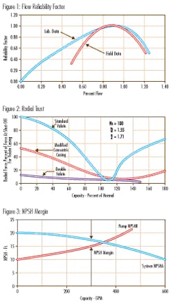
Figure 1 shows the reliability impact of operating pumps at or near their best efficiency flow rates, based on controlled laboratory tests and actual field experience. The laboratory tests were conducted on three API end suction pumps (average flow rate of 1,700 gpm), where pump reliability was inferred by pressure pulsation (noise) levels. The field data curve is a trend line derived from maintenance MTBF data collected on 48 large split case pumps (average flow rate of 3,000 gpm), in a large process plant. One of the three API pumps and the majority of the split case pumps had high suction energy (see October 2007 column). As can be observed, pump reliability peaks at about 90% of the best efficiency flow rate and falls off very quickly away from this flow rate, especially at higher flow rates.
The reasons for this fall off in pump reliability are many, and some-what dependent on the pump type and energy level. The primary factors are:
1. Temperature Rise: At low flow rates, below around 10% of the best efficiency flow rate, there is not enough flow through the pump to take away the heat from the input energy to the pump, resulting in thermal expansions that can cause internal metal contact and possible failure.
2. Bearing Life: Most centrifugal pumps use single volute casings. The volute scroll is designed for constant velocity near the best efficiency flow rate, which yields a uniform static pressure around the periphery of the impeller, at this flow rate. However, as the flow rate moves away from the BEP, the pressure distribution around the impeller changes, resulting in high radial loads on the pump bearings, as shown in figure 2. Since antifriction (ball or roller) bearing life is a function of the cube of this radial load, bearing life drops off very quickly away from the BEP. Double volute casings are used on some larger pumps to minimize this radial load.
3. NPSH Margin: As discussed in the October 2007 column, a sizable NPSH (Net Positive Suction Head) margin is required above the published net positive suction head required (NPSHR) of a pump, to prevent potentially damaging cavitation within the pump, (primarily a concern for High Suction Energy Pumps). For maximum reliability with high suction energy pumps, the NPSH margin should be between 1.3 and 4.0, depending on the suction energy ratio. However, because the NPSHR of a centrifugal pump increases with increased flow rate, and the NPSHA (Net Positive Suction Head Available) by the system decreases with increased flow (see figure 3), the NPSH margin decreases rapidly with increased flow, especially beyond the BEP of the pump, thus quickly reducing pump reliability.
4. Suction Recirculation: Suction recirculation, which occurs in all centrifugal pumps at some reduced flow rate, is a condition where the flow in the inlet portion of an impeller is separated from the vanes and ejected upstream, opposite to the direction of net flow entering the impeller. It forms eddies and vortices within the impeller inlet (which can cause cavitation), and pre-rotation of the liquid entering the pump.
As discussed in my October 2007 column, suction recirculation may or may not cause noise, vibration, erosion damage, and/or large forces on the impeller (which can affect shaft seal and bearing life). The likelihood of damage is heavily dependent on the suction energy (high or very high), and NPSH margin. The start of suction recirculation (minimum stable flow rate) is dependent on the Suction Specific Speed, Specific Speed and specific pump design. For high suction energy pumps the start of suction recirculation generally ranges from 40% to 100% of the BEP flow. High suction energy pumps should not be operated at flow rates below the start of suction recirculation.
5. Shaft Seal Life: The shaft seal is generally the weakest link in a centrifugal pump. They are negatively impacted by all of the above off-design operating conditions. Shaft deflection (seal face movement), caused by high radial loads from the non-uniform volute pressure distribution (Fig. 2) at off BEP conditions, lowers shaft seal life. Increased vibration from the mismatch of the liquid direction entering the impeller and casing cut-water, with the metal vane angles, at operations away from the best efficiency point, further reduces the shaft seal life. Finally, air and vapors liberated below an NPSH margin of 1.1 to 1.3 can have a negative impact on shaft seal life, even with low suction energy pumps.
The above underscores the importance of not over-sizing pumps for their applications, by piling on too much safety margin, which will cause the pumps to operated at reduced flow rates below the preferred operating region. Once installed, pump operation can normally be moved closer to the BEP by selecting (changing to) a more appropriate impeller diameter.
About the Author:
Allan R. Budris, P.E., is an independent consulting engineer who specializes in training, failure analysis, troubleshooting, reliability, efficiency audits and litigation support on pumps and pumping systems. With offices in Washington, NJ, he can be contacted via e-mail at [email protected].