By Allan R. Budris
I have had more response to my August 2009 column on pumps operated as turbines (PAT) than any of my other Pump Tips columns, many asking about specific applications. In response I thought that I would expand a little more on this energy savings topic in this month's column.
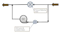
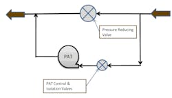
Figure 1: Schematic diagram for pump-as-turbine installed in parallel with a pipeline pressure reducing valve
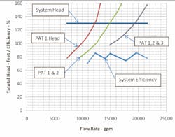
There are situations where step-less, infinitely variable flow, with constant speed and head, is required from a PAT installation. A common application for a pump as a turbine of this type would be as a pressure-reduction machine in a municipal water supply. Water may flow down from a mountain reservoir, or water tower, with a relatively constant pressure, but the flow will vary during the day as a function of the resident's requirements. A pressure-reducing valve (PRV) with flow control most likely exists in the pipeline to break down the pressure while controlling the flow. A Pump-as-Turbine (PAT) should be installed in parallel with the valve, as shown in Figure 1, to recover the lost energy. The system head curve and PAT head curve, along with their efficiency curves, for this type of application are shown in Figure 2.
Figure 2: Variable-flow system with constant head, utilizing a single constant-speed pump-as-turbine.
At a flow of 18,400 gpm, the pump-as-turbine curve and system curve match exactly, at the turbine best efficiency point. However, in order to reduce the capacity to below 18,400 gpm, the turbine control (& isolation) valve must be partially closed, which makes up the difference in head between the system curve and the pump-as-turbine curve. To achieve flows above 18,400 gpm, the turbine control (& isolation) valve must be opened completely, and the existing pressure reducing valve (PRV) opened slightly to act as a bypass valve.
The system just described is quite sufficient for many applications. However, note that because some head is still wasted in valving, the system efficiency is not optimum. Further, as noted in the August "Pumps as Turbines" Column, the output power (bhp), and therefore the efficiency of a constant speed, constant head PAT goes to zero at approximately 40 - 42 percent of the turbine best efficiency flow rate. Energy must be added to the hydraulic turbine in order for it to rotate (at constant speed) at flow rates below this capacity. It is for this reason that hydraulic power recovery turbines tend to be selected to operate near or above the turbine best efficiency point (bep). To further improve the efficiency, multiple pumps-as-turbines could be used.
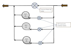
Figure 3: Schematic diagram for a multiple pump-as-turbine, variable flow system
By installing multiple pumps, optimum efficiencies can be obtained from each on-line unit. Depending upon water flows, different pump units can be turned on or off to match inflows. This means that there are much lower losses from inefficiencies in throttling the pressure reducing or by-pass valves. Also, in case of repairs to one of the units, the only downtime will be the actual unit that is being serviced, allowing the others to keep working. With one main large PAT, if it breaks down, there is 100% loss in energy savings.
Figures 3 and 4 demonstrate how a system of this type could operate. At flows between 10,800 and 12,100 gpm, only Turbine 1 would be running, and its control valve would be partially open. At flows between 12,100 and 13,900 gpm, Turbine No. 1's control valve would be completely open, and some of the flow would bypass into Turbine No. 2. When Turbine No. 2 reached synchronous speed, it would also be started up. This sequencing would continue until full flow was achieved. Note the improvement in the system efficiency with this multiple pump-as-turbine configuration.
Constant speed applications are common, since the generators driven by a PAT are often interconnected to a utility, which means that the generators must operated at synchronous (60 hz) speeds. This also allows for the use of an induction motor for the generator, which is very cost effective. It works quite well when interconnected to a utility, as an induction system requires no governor controls. The induction motor, instead of consuming energy, is driven at 50 RPM over its rated speed and the motor becomes a generator. Induction generators are much less expensive than other types of generators, but require excitation to operate. This is why they are ideally suited for interconnected utility applications.
Another type of constant speed PAT application is where a PAT is installed in tandem, on the back end of a double extended motor shaft, and the motor is driving some other piece of equipment, such as a pump. The power generated from the PAT would, therefore, unload the electric driven motor. No separate speed control system would be required for such an installation, since the motor would control the speed. An overrunning clutch may want to be added to a tandem installation in order to disconnect the PAT during low flow operation, when the PAT would be absorbing instead of inputting power to the system.
Finally, I would be interested in any other Pump-as-Turbine applications that my readers would like to share. WW
More WaterWorld Current Issue Articles
More WaterWorld Archives Issue Articles
