Avoiding Arc Flash Hazards in the Water Industry
Philip M. Gonski
Nearly 80% of all electrical related incidents in the industrial sector are the result of arc flash, resulting in over 600 fatalities and 30,000 injuries a year. An estimated 5 to 10 arc flash injuries occur every day, with treatment estimated to exceed $1 million per case. Although the probability is low of arcing occurring, the potential damage to both employees and facilities can hardly be ignored.
Until recently, electrical safety standards primarily revolved around preventing fires and electrocution of employees. Increasing arc flash awareness in the industry culminated in a major revision of the NFPA standard in 2002, mandating the use of arc flash hazard labels on equipment. Employers may often falsely believe that since arc flash is not specifically mentioned, nor enforced, in OSHA standards, that proper training and labeling are not required. However, failure to provide adequate safety training and labels exposes employers to full liability under the OSHA "General Duty" clause.
Arc flash is a flashover of electrical current through the air from a live conductor to another and oftentimes to ground. The temperature generated can reach 35,000 F, greater than the surface of the sun. In addition to the extreme temperatures generated, employees have been thrown across rooms and suffered permanent hearing loss due from the accompanying sound blast from the explosion. In many of these cases, the employee would have been protected from harm if the employer had stressed proper usage of safety equipment and procedures.
Due to the nature of arcing faults, they are inherently difficult to predict. However, there are key risk factors which can significantly increase the likelihood of an event. Unfortunately, many water and wastewater facilities must remain in continual operation to keep pace with water demand and are unable to have a complete plant outage. Consequently, the risk of an arc flash incident occurring is substantially greater, as employees must perform work on energized equipment.
The moisture-filled environment typically encountered in the water industry significantly increases the risk of an arc flash incident. If electrical equipment is continually exposed to a damp environment, it increases the likelihood of a moisture track developing between two electrical phases. Under ideal conditions, this could quickly proliferate into an electrical fault. It is thus critical for facilities to ensure that equipment panels located in damp or wet environments are properly rated, as well as ensuring that all conduits are sealed.
Many of the risk factors for arc flash hazards can be prevented by proper preventative maintenance procedures. However, with the inability to have complete outages, regular maintenance overhauls on equipment can be difficult to schedule.
NFPA 70E Task Tables
Can we simply use the NFPA 70E Task Tables in determining an arc flash hazard? The "simple" answer is yes and no. NFPA 70E defines many of the typical tasks in which workers will perform on electrical equipment and the corresponding safety equipment. Although this enables employees to have a general idea of what protection they require, the task tables are not based on the actual electrical system. Consequently, using the task tables may result in employees being either under protected or overprotected. While one might believe being overprotected is a fine idea, it prolongs the time an employee performs tasks and their exposure to potential hazards. The only way to accurately define the proper protection is a detailed Arc Flash Hazard analysis performed as per IEEE 1584.
Arch Flash Hazard Analysis
To coincide with a planned major upgrade, a large wastewater facility decided to perform an arc flash hazard analysis and coordination study. Safety of employees, as well as compliance with national codes, was at the forefront of their decision.
The first step toward performing an arch flash calculation was to contact the local utility and obtain short circuit information. It is critical to judge whether they are giving "realistic" values, or just conservative maximums, since higher short circuit values can often result in lower arc flash hazards.
Similar to many wastewater facilities, plant single line diagrams had been provided for the plant on a "contract by contract" basis for all of its retrofit projects. After over 50 years of operation, the facility had accumulated multiple versions of single line diagrams, often depicting conflicting information. Many critical locations contained no documentation on the existing electrical system, or any record of their construction.
From an operations standpoint, troubleshooting was exceedingly complicated, as none of the drawings could be trusted. The only real way to gather input for the arc flash study was to field verify what was actually present and reconstruct the entire electrical system.
Keeping in line with the recommendations of IEEE 1584, all cable sizes and lengths, equipment nameplates, breaker settings, equipment model numbers, and motor information was gathered for equipment greater than 50 hp at 480V. With the exception of 120/208V panels powered from transformers greater than 125kVA, low voltage panels were ignored as their available energy is not enough to sustain an arc.
As is the case with most arc flash studies, the data gathering phase was perhaps the most costly and time intensive. Costs associated with data collection are often drastically reduced if the facility cans provide the engineer with photographs and documentation on the equipment.
After reconstructing the plant single line diagram and discussing operating scenarios with operators, the system was modeled using commercially available engineering software. Equipment device settings were visually displayed and interpreted by the engineer based upon industry standards, as well as engineering judgment.
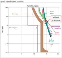
Severe device incoordination was immediately noted. Ideally, devices nearest an electrical fault should operate first, with the upstream device responding only if the downstream device failed to operate. This enables the healthy portions of the system to remain in operation, while the unhealthy portions are removed. In the example illustrated in Figure 1, a fault on the MCC bus would have been cleared by the blowing of the upstream transformer after a delay of over 50 seconds. This slow response likely would have resulted in the complete destruction of the equipment.
Device settings similar to the above example are all too common, as contractors often do not possess accurate short circuit information at the time of their installation. In the absence of information, as well as to ensure the motors supplied on their project will start, breakers are set to the highest possible setting. Unfortunately, doing so can lead to significant delays in responding to faults, and substantially increase the risks to employees.
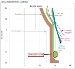
After modeling and analyzing the system, in this particular example, the engineer was able to lower the dial on the MCC breaker to clear a fault using the MCC main breaker in less than .1 seconds (Figure 2). This resulted in lowering the arc flash hazard from a "3" to a "0", and still allowed the starting of the motors.
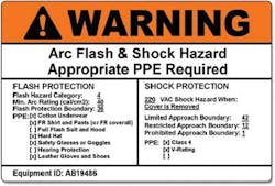
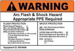
Once the results were finalized and discussed with operators, warning stickers were printed and installed on the equipment. Although there are many varieties of stickers available, at the least stickers should specify the hazard category, and required safety apparel for live electrical work.
At the conclusion of the overall study, the facility possessed a complete and accurate set of single line diagrams, along with safety procedures that were permanently located near the equipment for operator use. On future projects at the facility, contractors will now have accurate short circuit information to properly set protective devices.
Conclusion
Facilities are under continual pressure to keep pace with the latest OSHA/NFPA regulation, as well as deal with staff cutbacks and increased operational demands. Arc Flash hazard analysis provides a valuable insight into system operations and provides other peripheral benefits such as accurate single line diagrams, protective device optimization, and discovering any potentially dangerous conditions.
Preventing long term outages and promoting employee safety are the ultimate goals of arc flash calculations. While the engineer can often drastically reduce arc flash hazards by modifying device settings, recommending current limiting fuses, zone interlocking, or differential protection, there is never a substitute for the value of preventative maintenance and safety training.
About the Author: Philip Gonski, PE, is an Electrical Project Manager at the Keystone Engineering Group in Frazer, PA, serving the electrical needs of the water and wastewater industry. His background is in power system design, protective relaying coordination, and arc flash hazard assessments. He can be reached at [email protected]


