The Big Picture: Computer Modeling Optimizes Mixer Design and Water, Wastewater Treatment Plant Performance
By Jim Maxon, Stephen Fowler and Richard Kehn
Plant owners and operators must be aware of innovative and current methodologies to solve their water and wastewater treatment and operations problems. As such, suppliers with sophisticated software models can anticipate potential limitations and enhance treatment system hydraulics.
What are the incentives? These investigations create large opportunities for productivity and cost savings, such as minimizing capital costs, controlling mechanical spares, maximizing equipment uptime in anoxic basins, and locating basin inlets/outlets to prevent short-circuiting.
Vertical turbine mixers - whether flash/rapid mixers, flocculators or anoxic or digester mixers - contribute to the success of these efforts. Likewise, mechanical mixers can be modeled in water and wastewater operations using computational fluid dynamic (CFD) techniques. CFD is the branch of fluid mechanics where flow fields are modeled and numerically solved using computers. Understanding fundamental fluid dynamics is required to ensure the proper use of CFD as a design tool. This includes applying the correct model to the situation (laminar versus turbulent regimes), employing sound volume meshing techniques, and applying appropriate boundary conditions to the basin geometry under evaluation, as well as experimental validation of CFD results from the mixer's impeller characteristics and performance.
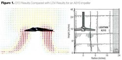
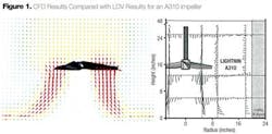
Water and wastewater treatment basins present special atypical geometries to evaluate. Mixers can be modeled using either two dimensional (2-D) or three dimensional (3-D) CFD techniques. 2-D modeling is suited for axisymmetric geometries and requires knowledge of the mixer's impeller outlet velocity profile. Further, it can provide a quick approximation of the flow pattern in the mixing tank and is often useful to make rapid decisions. 3-D modeling, however, uses the actual impeller geometry and considers the rotation of the impeller, thus generating the correct flow pattern (see Fig. 1).
Experimental validation of the actual impellers used must be available to validate the predictions of the CFD model. The CFD designer needs to have access to both pilot and full-scale fluid tanks to perform these experiments.
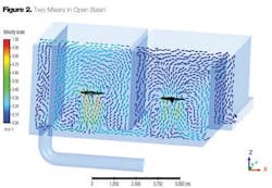
A multitude of case histories can be documented and explored, with two highlighted in this brief summary. In the first case, the concentration is directed toward potential or predicted short-circuiting in a large basin with two clockwise rotational mixers (see Fig. 2). Had such short circuiting existed, the project would have been delayed with costly modifications. CFD analysis focused on the system-specific hydraulic flow rate, impeller diameter/tank span ratios of the two mixers, and basin geometry with its exact inlet and outlet positioning. Those specific conditions confirmed that no basin or mixer change was warranted, costly delays were avoided and the project remained on schedule.
A multi-train flocculation design presented more complicated interactions to be resolved. Moreover, the mixer design comparison incorporated a continuous system. The specifications required multiple mixers per train of tanks with alternating rotation of impellers. The engineering approach in minimizing short-circuiting of the water entering the inlet gate of the train - and consequently to ensure optimal mixing - indicated it was better to circulate through the impellers first before leaving the tank at the very end. This proposed installation would then have required a series of clockwise and counterclockwise impellers. Further, the physical difference of the design would have added complexity and cost to the installation.
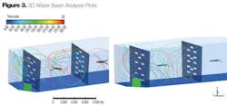
3-D CFD compared both systems, with one operating as specified and the other containing all clockwise rotating impellers. The plots in Figure 3 show the paths the water will take as it enters the gate. They show a similar behavior between both systems and conclude that no measurable difference between the two could be found. Given the flow of the system and the exact geometry of the trains and tank baffles, a solution was quickly found. Equipment costs were reduced with CFD certainty.
Other wastewater applications where CFD can be helpful include handling the fibrous solids on mixing impellers (referred to as "ragging"), and retrofitting into existing basins the proper mixer design for inlet and outlet locations. Advanced computer modeling, which rests on testing facilities and experimental validation of existing impellers, will optimize mixer design and significantly improve water and wastewater treatment plant performance.
About the Authors: Richard Kehn is manager of research and development and James Maxon is senior application engineer at SPX Flow Technology. Steve Fowler has worked directly and as a manufacturer's rep owner with SPX's LIGHTNIN brand since 1978. SPX Corporation is a member of the Water and Wastewater Equipment Manufacturers Association (WWEMA).


