The Missouri River evolves steadily from a swift trout stream in Montana into a turbid highway for barge traffic by the time it passes MidAmerican Energy's George Neal Energy Center south of Sioux City, IA. The Neal North complex and a sister station two miles away designated Neal South, are among the seven power plants that MidAmerican Energy operates along Iowa's stretch of the Missouri River to serve 690,000 customers.
Even with six dams upstream from the plant, the Missouri River can still unleash floods or shrink from drought and manipulation of its flow. The river serves many roles – recreation, agricultural, community drinking water and barge commerce – and is the very lifeblood of power plant facilities like the Neal Energy Center.
Slaking Neal's Thirst
The often-low river level at the 515-megawatt Neal #3 intake during winter months has concerned plant operators for many years. Extended drought and more conservative releases from upstream reservoirs controlled by the U.S. Army Corps of Engineers have limited the river's flow during winter months. Ice jams in the shallows near Ponca, NE, can further aggravate the problem.
MidAmerican Energy needed an effective engineering solution to ensure a reliable flow of cooling water to Neal #3, the largest – and most vulnerable – of three units located at Neal North.
"Neal #3 requires the most cooling water but also is the most susceptible to low river stages," said Kevin Calloway, plant mechanical engineer with the Generation Engineering Department. "We've experienced flows low enough to have forced it off line in the past.
"When that happens we lose over 12,000 megawatt-hours each day – over half of Neal North's capacity," he said. "That's a big financial hit to the utility, especially when we're forced to buy replacement power on the open market."
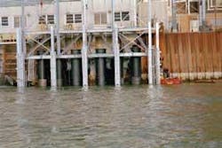
The 135-megawatt Neal #1 consists of a cyclone-fired boiler while the 300-megawatt Neal #2 and Neal #3 have pulverized coal boilers. All three rely on a once-through cooling water system. Neal #1 and #2 share a common intake structure, while Neal #3 has a standalone intake located 200 feet upstream.
Under normal conditions, cooling water is drawn from the river for Neal #1 by two 37,500-gpm vertical pumps while Neal #2 relies on twin 65,000-gpm vertical pumps. Two 145,000 gpm vertical pumps supply Neal #3. These permanent circulating water pumps for Neal #3 require 8-1/2 ft. of submergence, compared to 6 ft. for Neal #1, and 5 ft. for adequate submergence to serve Neal #2. The floor of the intake structures are at elevation 1,045.25 ft. above sea level, with the base of the pump bells at elevations of 1,046.7 ft. for Neal #1, 1,048.25 ft. for Neal #2 and 1,047.5 ft. for Neal #3.
First Response – Ensure Flow
The first measure to restore reliable winter flow involved a vacuum lift system installed in 1982. This mechanically boosted submergence to Neal #2 and Neal #3 pumps whenever the water elevation declined below elevation 1,056 by raising the water level in the pump chamber by about seven feet. The pumps could then operate even when ice jams upstream of the plant limited flows downstream enough to cause vortexing and cavitation without the vacuum lift. The improvement supplied sufficient cooling water, but the pumps continued to trip even when the river elevation stood at 1,052 ft., largely due to air sucked under the vacuum lift wall that prevented adequate submergence. Restarting the Neal units was then challenging because the intake bar and traveling screens often froze over quickly when the pumps were off-line, and there was no discharge from the return warm water line.
Unreliable flow at the intakes became especially pronounced during the extended drought from 1994 through 1999. The receding reservoir capacity, impact on wildlife habitat and pending environmental regulations led the Corps to reassess winter release practices to ensure the impoundments stabilized and retained sufficient winter storage to recharge the river channel for summer barge traffic. Mean annual discharge during the April 1 to Nov. 30 navigation season declined from the historic norm of 26,600-31,000 cfs to 12,000 cfs. The reduced river levels at the Neal North intakes exposed the three, coal-fired Neal units to potential operational failure, especially the crucial generation from Neal #3, during the winter months. The diminished flow has presented the same threat at the plant intakes of other power and water utilities farther downstream along the Missouri River.
Studied Alternatives
The amended flow management strategy by the Corps frequently left sandbars visible in the vicinity of the intake. The reduced winter flow and anticipated changes in environmental regulations that may ultimately affect power and water plants that draw from the river, sent MidAmerican Energy's management and engineering consultants, Burns & McDonnell, searching to develop and implement an effective response, Calloway said.
Calloway led the project that initially focused on a range of alternatives. These included vacuum lift systems, suction scoops, a new consolidated intake served by a deep supply channel, replacement of the Neal #3 intake, conversion to a closed-loop design, and the addition of a supplemental pump system. Detailed modeling and analyses applied to each option, including: conceptual layouts; construction schedules; cost/benefit and life cycle operation; and maintenance costs. The preliminary work also took into account estimated revenue loss from Neal outages when offset by the reliability improvements gained from each alternative. A 20-year life cycle was used to identify the lowest cost measure, including status quo operations.
The studies concluded that the only long-term solution was building a new consolidated intake to serve all three units at Neal North. MidAmerican Energy and Burns & McDonnell based that decision on the station's contribution to the utility's total system and the likelihood continued degradation of the river could force the Corps to reduce summer release rates.
The $40-million commitment to build a new intake, however, not only presented challenging construction conditions but could be compromised while under way by final EPA 316(b) regulation modifications in the Clean Water Act that govern cooling water intake structures, whose new provisions were likely to influence power plants (see: www.epa.gov/waterscience/316b/).
MidAmerican Energy therefore authorized Burns & McDonnell to design a supplemental pump system with sufficient interim capacity to ensure reliability at the Neal #3 intake during low river conditions.
"Other utilities operating plants downriver that face similar conditions have visited us and may pursue a similar supplemental system," Calloway said.
Cost Efficiency
The utility opted for the $3.5 million supplemental system after testing a single pump during the summer of 2001. Electric Pump, a Des Moines-based factory representative for ITT Flygt, subsequently supplied the six pumps applied to the system – which had to be removable seasonally. The utility installs and operates the system from October through late March. With the onset of the navigation season for barge traffic, the Corps then requires removal of the eight, armor-plated construction barges linked when afloat to create an ice shield around the system. Once the barges are pulled, the utility also must remove the pumps and framework of the supplemental system to protect it from potential damage by floating debris during high water incidents, Calloway explained.
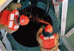
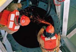
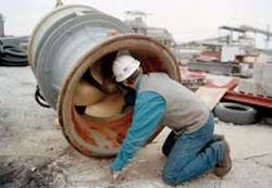
The system consists of six ITT Model PL7101 axial flow submersible pumps that nest into fabricated 48'' tubes mounted to the removable framework cantilevered off the front of the intake. The other components include a 10-gauge, 1/2-inch stainless steel mesh barrier encircling the system, an overhead monorail system for installation and removal of the 240-HP pumps, and a warm-water discharge splash plate. The utility also installed a 2500/3125 KVA 4160 Volt substation to serve the system and provide future capacity for other needs.
The pump tubes have a bottom plate that limits debris carried along the river bottom from invading the pumps during operation. The base of the tubes is set at elevation 1,045 ft., which should ensure operation down to elevation 1,049. Merely lengthening the tubes could overcome further river degradation.
The utility selected these particular pumps to achieve a high volume of water at low-head conditions. Five of the 37,000-gpm pumps operate in unison while the sixth is cycled as a reserve. They function at approximately 80% hydraulic efficiency even with minimum submergence. The 220,000-gpm discharge from the tubes into the existing intake has maintained adequate water level in the wet well for the circulating pumps.
In addition to their acceptable cost, modest operational expense and reliable performance, the use of submersible pumps also eliminated the need for wet well reconstruction. The supplemental system mounted to the removable framework was favored over barge-mounted horizontal axial flow pumps. The utility achieved less exposure to floating ice, eliminated a temporary power line to the barges and the need to run a warm water delivery line to prevent the screens from freezing. Maintenance is also easier with the submersible pumps mounted off the front of the intake.
Neal #3 requires only one circulator pump in winter because the river water temperatures drop to 50°F or less. New roller gates installed in the stop gate slides between the bar screens and traveling screens maintain an adequate water level in front of the vacuum lift walls and in the circulator pump bay. The discharge line from the supplemental pumps runs above the lowest bar screen section and discharges above the roller gates at elevation 1,061 ft. The water level inside the intake remains constant at 1,065 ft.
Conclusion
The supplemental system had clearly passed the test of time by operating reliably for the second season when it was removed for the 2004 navigation season.
"The operations manager said the system kept us on line a couple of times this past winter when we would have been forced off," Calloway said. "We now feel we have some breathing room during low river stages. The 1,050 elevation would be the ultimate test and the river already reached 1,051.7 ft. last January."
The supplemental pump system adopted by MidAmerican Energy offers an effective response to conditions that might otherwise compromise the plant's operation. Meanwhile, Mid- American Energy continues to monitor the twofold implications of potentially changing EPA and Army Corps of Engineers policies before breaking ground on the new channel and consolidated intake.


