by Allan R. Budris
All rotating machines, including pumps, vibrate to some extent due to response from excitation forces, such as residual rotor unbalance, turbulent liquid flow, pressure pulsations, cavitation, and / or pump wear. Further, the magnitude of the vibration will be amplified if the vibration frequency approaches the resonant frequency of a major pump, foundation and/or piping component. The issue of interest is not whether or not the pump vibrates, but:
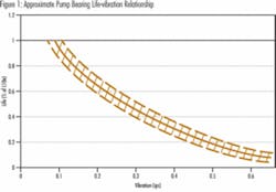
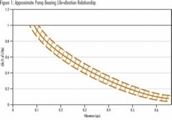
- Is the amplitude and/or frequency of the vibration sufficiently high to cause actual or perceived damage to any of the pump components (see figure 1), or
- Is the vibration a symptom of some other damaging phenomenon happening within the pump?
Various industry organizations, such as the Hydraulic Institute (ANSI/HI 9.6.4), have set vibration limits to help guide users to avoid excessive levels of vibration in pumps.
Machinery vibration and its measurement are complex issues and require clarification.
1. Vibration can be in the form of rotor lateral vibration (such as from rotor unbalance), rotor torsional vibration (such as caused by VFD motor torque pulsations, or combustion engine torque spikes), and structure lateral vibration (the type most often measured).
2. Further, should vibration displacement, velocity or acceleration be measured and/or analyzed? The industry today and the Hydraulic Institute primarily use velocity (mm/sec and/or inches/sec).
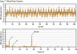
3. Should the “total all-pass” (unfiltered) or the “filtered” frequency be used? Most industry specifications and standards use “total all-pass” vibration values to identify problem pumps, with filtered values reserved for analysis of vibration problems (see figure 2). To analyze the problem you need filtered vibration to identify the offending frequencies. This can often point to the specific problem.
4. Should RMS (root mean square) or peak-to-peak values be measured or specified? The Hydraulic Institute has chosen RMS acceptance limit values, since most vibration instruments actually measure vibration in RMS terms, and calculate peak-to-peak values if required. RMS values are roughly 0.707 times zero-to-peak values. However, this relationship applies only for vibration consisting of a single sine wave. For more complex waveforms, this conversion does not yield correct results.
5. What is the acceptable vibration amplitude (new) for a particular application? Should acceptance limits change along with overall pump power and flow-rate regions? The Hydraulic Institute currently bases acceptable vibration limits on pump type, power level, and whether the pump is on the factory test stand or in the field. The HI standard will soon also include separate acceptance values for the “preferred” (70% - 120% of bep) and “manufacturer’s allowable” operating flow regions. A vibration velocity of 0.15 ips for field measurements, for horizontal clear liquid pumps represents a “rule-of-thumb,” as-new acceptance value for pumps up to 200 bhp. For horizontal solids –handling pump types, the new HI limit will be 0.25 in/sec (below 33 bhp), 0.28 in/sec (above 33 bhp but below 100 bhp), and 0.31 in/sec (for 100 bhp and above), all in the preferred operating range, tested with clear liquids.
6. How do factory test stand vibration measurements compare with field site values? What is the effect of foundation stiffness / grouting? Generally, the stiffness of a field pump foundation is much higher than found on a factory test stand, especially if the pump base plate is grouted. That is why the Hydraulic Institute’s new (2008) vibration standard will allow higher test stand values in the preferred operating region (up to 30% higher values outside the preferred operation region, but within the allowable operating flow range).
7. How much has the vibration amplitude and/or frequency changed during the life of the machine? It is helpful to have an as-new vibration signature taken and kept on file for future use. Normally, attention should be given a pump when the vibration amplitude increases by a factor of two compared with the as-new readings.
8. Location of vibration measurements: The vibration transducers should be mounted in such a way as to not adversely affect the accuracy of the measurements. In general, the vibration probes should be located approximately at the middle of the bearing housing of between-bearing pumps, near the outer bearing of end suction pumps, and near the top of the motor support for vertical wet pit pumps. The bearing housing vibration level recorded shall be the maximum of measurements taken in each plane (vertical, horizontal and axial directions).
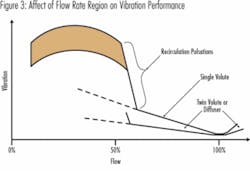
9. In order to obtain viable test results, there shall be no suction-related adverse hydraulic phenomena (submerged vortices, free-surface vortices, preswirl, non-uniform velocity distributions at the impeller eye, entrained gas, cavitation, or flow field variations with time) present to an extent significant enough to adverse influence the vibration measurements (see figure 3), during vibration measurements. Also, the coupling alignment shall be in accordance with the pump manufacturers’ recommendations, and the nozzle loads should not exceed the manufacturer’s recommendations.
Causes of Excessive Vibration
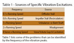
Once a pump has been determined to have a high “total / all-pass” vibration level, the next step is to identify the cause. Now is the time to obtain a filtered vibration analysis (see figure 2). The first step in the analysis should be to capture and then evaluate, the multiples of pump running speed.
Other possible causes of vibration may be more complex to analyze, among these are:
1. Operating speed close to the mechanical or hydraulic resonant frequency of a major pump, foundation or pipe component. This is a major importance with large multistage horizontal and long vertical pumps. A margin of safety should be provided between rotor or structural natural frequencies and operating speed. Typical margins are 15-25%. Vibration amplification will generally be greater than 2.5 times at a resonant frequency.
2. Poor pump suction or discharge piping can also cause increased vibration, normally by either increased cavitation or turbulence in the pump, or pump operating speed or vane pass frequencies could excite a piping structural or hydraulic resonance.
3. Bearing wear. Rolling element bearings have distinct vibration signatures based on the number of bearing balls or rollers. Contact bearing manufacturer for these frequencies.
4. Opening up of impeller wearing ring clearances, which can reduce the NPSH margin, and shift the pump operating flow point.
References:
1. “Pump User’s Handbook: life extension”, by Heinz P. Block & Allan R. Budris. Second edition, 2006, The Fairmont Press, Inc.
2. “Rotodynamic Pumps for Vibration Measurements and Allowable Values”, ANSI/HI 9.6.4-2008, Hydraulic Institute.
About the Author: Allan R. Budris, P.E., is an independent consulting engineer who specializes in training, failure analysis, troubleshooting, reliability, efficiency audits and litigation support on pumps and pumping systems. With offices in Washington, NJ, he can be contacted via e-mail at [email protected].
Correction: The April Pump Tips column included an incorrect statement on NPSH Margin. The sentence should have read: For High and Very High Suction Energy pumps, pump reliability increases with increasing values of the Net Positive Suction Head Margin (NPSH-Margin, which is defined as the NPSH-Available by the System divided by the NPSH-Required from the pump).
