Pump Piping Can Impact Reliability
By Allan R. Budris
The purpose of pump piping is to provide a conduit for the flow of liquid to and from a pump, without adversely affecting the performance or reliability of the pump. However, many pump performance and reliability problems are caused, or aggravated, by inadequate system piping.
Suction Piping
Generally speaking, suction piping is more critical to the performance of a pump then the discharge piping. The function of suction piping is to supply an evenly distributed flow of liquid to the pump suction, with sufficient pressure to the pump to avoid cavitation and related damage in the pump. An uneven flow distribution is characterized by strong local currents, swirls and/or an excessive amount of entrained air. The ideal approach is a straight pipe (of some minimum length), coming directly to the pump, with no turns or flow disturbing fittings close to the pump (see figure 1). Furthermore, the suction piping should be at least as large as the pump suction nozzle and be sized to ensure that the maximum liquid velocity at any point in the inlet piping does not exceed 8 ft/sec.
If the suction piping fails to deliver the liquid to the pump in this condition, a number of pump problems can result. High “Suction Energy” pumps (see October 2007 column), and high Specific Speed (over 3,500) pumps are most susceptible to poor suction piping. More often than not, the resulting problems can include one or more of the following:
- Noisy operation.
- Random axial load oscillations.
- Deterioration in performance.
- Premature bearing and/or seal failure
- Cavitation damage to the impeller and inlet portions of the casing.
- Occasional damage from liquid separation on the discharge side.
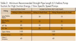
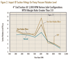
Figure 2 shows the results of a high suction energy pump tested with three separate inlet piping configurations (a straight inlet pipe, a single short radius elbow installed on the pump suction nozzle, and two short radius suction nozzles, at right angles to one another, installed on the pump suction). As can be observed, the lowest suction pressure level, in the low flow suction recirculation region, is with the straight pipe, while the highest pressure level in this flow region is with two perpendicular short radius elbows. These higher pressure pulsation levels are the result of higher levels of cavitation in the pump, caused by the reduced NPSH available from the flow disturbing fittings.
The most disturbing flow patterns to a pump are those that result from swirling liquid that has traversed several changes of direction in various planes. When fittings, such as elbows and “T” fittings (especially two elbows at right angles), are located too close to the pump inlet, spinning action or “swirl” is induced. This swirl could adversely affect pump performance by reducing efficiency, head and net positive suction head (NPSH) available. It also could generate noise, vibration and damage in high-suction-energy pumps. Straight pipe length recommendations should be doubled if the distance between two perpendicular elbows in the suction line is less then five pipe diameters.
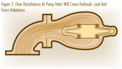
Eccentric reducers should be installed with the flat surface at the top (to avoid trapping air or vapors) and the slopped surface at the bottom, for horizontal pump installations (see figure 1). An exception to this is when a double suction, split case pump is installed vertically, in which case the flat surface should be at the side of the fitting to avoid flow disturbances extending into the pump, such as shown in figure 3 for a side facing elbow. Elbows must be vertical when installed close to a horizontal double suction pump.
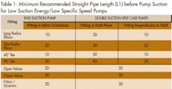
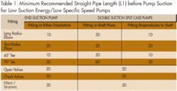
It is always recommended that a straight uninterrupted section of pipe be installed between the pump and the nearest fitting. Isolation valves, strainers and other devices used on the inlet (suction) side of a pump should be sized and located to minimize disturbance of the flow into the pump. The specific straight pipe length recommendation depends on the type of fitting(s), the pump type, the suction energy level and the pump specific speed. One to eight straight pipe diameters are recommended for low suction energy, low specific speed (below 3,500) pumps, see Table 1. Three to 16 pipe diameters are recommended for high suction energy and high specific speed (above 3,500) pumps, see Table 2.
If the minimum recommended straight pipe lengths cannot be provided, flow-straightening devices should be considered.
Discharge piping
System piping size, which typically is mainly on the discharge of the pump, is normally dictated by friction losses, which does have a life cycle cost impact. System piping is also influenced by process considerations, with the maximum recommended velocity at any point in the pump discharge piping being 15 ft/sec. Discharge piping flow characteristics normally will not affect the performance and reliability of a centrifugal pump. However, a few exceptions do exist, such as:
- High-discharge-energy pumps might be sensitive to flow-disturbing fittings mounted close to the pump discharge flange. High Discharge Energy pumps are pumps with high head (900 feet or above for pumps with specific speeds below 1,300). For higher specific speed values, the start of high discharge energy drops from 900 feet at 1,300 to 200 feet at a specific speed of 2,700, per the Hydraulic Institute.
- Sudden valve closures might cause excessively high water-hammer-generated pressure spikes to be reflected back to the pump, possibly causing damage to the pump, or other piping fittings.
- Discharge piping might affect pump starting, stopping and priming.
- The discharge piping configuration also might alter any discharge flow recirculation, which can extend into the discharge piping at very low flow rates. This could have a small effect on the head developed by the pump at low flow rates, possibly causing the pump H-Q curve to droop towards shut-off.
It is recommended that high-discharge-energy pumps have a minimum straight discharge pipe length of four to eight pipe diameters. The specific pipe length recommendation will depend on actual experience, the type of fitting(s) downstream of the pump and the pump discharge energy level.
References: 1. “Pump User’s Handbook – Life Extension”, Allan R. Budris & Heinz P. Bloch, Second edition, 2006, The Fairmont Press, Inc.
About the Author:
Allan R. Budris, P.E., is an independent consulting engineer who specializes in training, failure analysis, troubleshooting, reliability, efficiency audits and litigation support on pumps and pumping systems. With offices in Washington, NJ, he can be contacted via e-mail at [email protected].