By Allan R. Budris
The piping attached to, and leading to and from a pump, can have a marked impact on the reliability of a pump. A previous WaterWorld column (see Pump Tips, April 2009) covered the potential hydraulic issues associated with poor suction and discharge pump piping, and how to avoid their negative impact. This column delves into the potential mechanical issues (mainly excessive nozzle loads) associated with poor pump piping, which can be equally detrimental to pump reliability.
Facilities with low pump mean time between failures (MTBF) will not experience significant reductions in repair frequencies unless excessive pump pipe stresses are eliminated or at least maintained below the allowable pump nozzle load values.
Two of the more common detrimental mechanical effects from pump piping are the excessive nozzle loads the piping can place on a pump and the excessive nozzle loads that unsupported equipment such as valves or vertical inline pumps can place on the piping. Excessive nozzle loads can be caused by thermal expansion of the pipe, unsupported piping and equipment weight, and misaligned piping.
Problems Caused by Excessive Nozzle Loads
Nozzle loads affect pump operation in various ways. At low levels, the effects may be insignificant. At higher levels, nozzle loads can contribute to the following:
1. Coupling misalignment, which leads to:
a. Increased pump bearing loads, which decreases bearing life
b. Decreased coupling life
c. Increased noise and vibration levels
2. Shaft deflection, which leads to reduced mechanical seal life
3. Fatigue or failure of the pump and/or motor shafts
4. In severe instances, catastrophic structural failure of:
a. The pump casing
b. Pump hold-down bolts/supports
c. Pump nozzles
5. Pump casing gasket leaks
6. Pipe to pump flange leaks
7. Decreased mean time between repair or failure
ReducING Excessive Pump Piping Nozzle Loads
Proper piping and pump layout design and detailed analysis, prior to installation of the system, are absolutely essential to the life and reliability of a pump. It can ensure that nozzle loads remain below acceptable limits for the installed pumps. This is accomplished by providing a properly supported piping system, which minimizes field adjustments during installation, saving both time and money. Piping analysis is an extremely complex subject. Only a computer model can accurately determine where and what types of supports must be installed for stress-free installation.
Final installation of restraints and anchors should take place after the pump has been completely installed and all terminal and equipment connections are made. Provisions for final piping field welds close to the pump are being used by the best performing reliability-focused user companies to ensure that the piping system will present a near-zero load condition on the pump and meet the offset and parallel recommendations listed below. Pump users should contact the pump manufacturer and/or review industry standards for the maximum allowable pump nozzle loads.
System piping should be led and installed to within 10 to 15 feet of the pump nozzles. The remaining pipe runs should then start with pipe flanges and reducers first being placed on the pump nozzles, and then piped away from the pump toward the main pipe runs.
Flanges of connecting piping should never be allowed to be "sprung" into position. Pipe flange bolt holes must be lined up with nozzle bolt holes within the limits of the flange bolt hole manufacturing clearance to permit insertion of bolts without applying any external force to the piping. The use of come-alongs, chainfalls, or other means of pulling piping into place to align the piping with the pump flanges is simply not acceptable.
Remember, the pump manufacturer's allowable pump nozzle load limits should never be exceeded. Computer piping analysis should be performed, with proper supports, loops and anchors, etc., considering system temperature extremes. If not available from the pump manufacturer, the Hydraulic Institute lists required allowable nozzle loads for various pump types.
Minimizing Nozzle Loads
Here are some of the specific key mechanical piping installation actions that can and should be taken to minimize pump nozzle loads to avoid a negative impact on the pump MTBF.
Baseplate and Pump Drive Unit Set:
Before connecting any piping to the pump make sure that:
- The baseplate is set and the grout has cured and hardened.
- The pump and driver are aligned, and tightly bolted in place.
Piping Support:
- All piping must be independently supported from the pump and drive unit so that the pump does not carry any piping weight.
- The piping supports must be able to carry the weight of the pipes and the liquid in them.
- The pipe support system must also be designed to accommodate any thermal expansion or contraction of the system by using expansion loops or expansion joints.
Connecting the Piping:
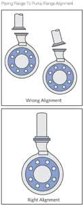
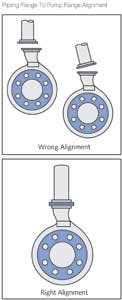
The pipe flanges and pump flanges must be aligned so they are straight and parallel to each other before being bolted together (see Figure). The general rules for pipe separation are:The above should ensure that the piping system will be within allowable pump nozzle load requirements, prior to hydro-test and start up.
Pump Piping Summary Checklist
So in summary:
- Field fit and weld suction piping the final 10-15 feet after pump is grouted and aligned, then pipe away from the pump to meet suction and discharge pipe. You should be able to move piping by hand to align with the pump, without the use of a crow-bar or other mechanical means.
- Check to see if proper pipe supports are installed.
- Tighten piping flange bolts in criss-cross pattern.
- Check discharge flange for level in two planes.
- 0.001 inch/foot maximum.
- Check parallelism of suction and discharge piping flanges.
- 0.010 inch maximum at gasket surface.
- Check concentricity of suction and discharge piping at the pump flanges
- Flange bolts must slip into place by hand.
- Check pump shaft deflection during flange bolt tightening. Maximum allowable deflection is 0.002 inches.
References: "Pump User's Handbook – Life Extension," Allan R. Budris & Heinz P. Bloch, Third edition, The Fairmont Press, Inc., 2010.
About the Author: Allan R. Budris, P.E., is an independent consulting engineer who specializes in training, failure analysis, troubleshooting, reliability, efficiency audits and litigation support on pumps and pumping systems. With offices in Washington, NJ, he can be contacted via e-mail at [email protected].
WaterWorld Articles Archives


