Most likely you don't even think about sewer systems until torrential rain elevates water to curb level. Unfortunately, the sewer systems beneath more than 770 older American cities create pollution problems during heavy storms. These older designs used cost-effective, single-style pipes for both sewage and storm runoff, sending the combined sewage overflow (CSO) into rivers and lakes in an approach that predates modern health and environmental concerns.
The 20th-century construction of sewage treatment plants brought new awareness to what could and should be done with residential, commercial and environmental runoff outflow. During normal operation, CSO discharge is transferred directly to treatment plants. During major storms, to avoid over-capacity problems at those plants, built-in relief structures called regulators still discharge excess flow into nearby waterbodies. These discharges carry a range of pollutants from oil and grease to pesticides and wildlife waste.
In 1994, the Environmental Protection Agency (EPA) issued a policy requiring the affected municipalities, mostly in the Northeast and Great lakes regions, to reduce or eliminate CSO-related problems. New CSO separation, storage and treatment facilities have already made a 67-percent improvement against the effects of pollution, but work remains. For Indianapolis, that effort began in 2008 when the city's Department of Public Works prepared a CSO long-term control plan. The core of their "storage and transport" approach, which will hold the overflow until the normal treatment plants can handle it, is called the Indianapolis Tunnel Storage System, or DigIndy.
This system, running a combined 25 miles, includes a massive underground pumping station and interconnecting structures that vertically drop CSO down from the existing sewer lines. For the first tunnel, three large drop structures divert CSO into the storage tunnels for subsequent treatment after rainfall subsides.
Indianapolis knew it needed to work fast to address the problem by the 2025 deadline. The city called upon AECOM to design the first of three deep-rock storage tunnels that Citizens Energy Group is building.
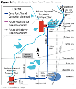
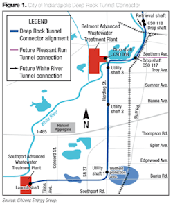
The first phase of this system is a $180-million project, called the Deep Rock Tunnel Connector (DRTC). DRTC is a seven-mile-long, 18-foot-diameter underground tunnel that will rework the flow path of three existing Indianapolis sewer-to-river outflow connections (see Fig. 1). The goal is to safely redirect excess rainfall runoff away from these relief outlets into massive tunnels, via drop structures between the existing sewers and new tunnels, and hold it until it can be pumped to a treatment plant for post-storm treatment.
At an average depth of 250 feet below ground surface, the DRTC is designed to minimize disruption to the neighborhoods above it during both construction and ultimate operation. But the size and complexity of the project added urgency to AECOM's task: design and evaluate possible drop structures for each of the three locations, finishing 60 percent of the structures' designs in seven months.
Consultant Ryan Edison, an AECOM senior technical specialist, knew that the contract's scheduling requirement would limit any physical build-and-test activity to just one model for validation only. AECOM chose FLOW-3D computational fluid dynamics (CFD) software from Flow Science to simulate the behavior of multiple possible drop-structure designs, minimizing the need for rework on the one physical model budgeted to be built and evaluated. Having used FLOW-3D for 15 years on major construction projects, he was confident that its ability to predict turbulence, overtopping and energy dissipation would be well suited to the design project.
Despite the time constraints, Edison was pleased with the challenge because of an unusual opportunity: creating the drop-structure design with CFD as well as following up with a physical study. "Because these are such big structures," he said, "there are not many of them built, and they're usually just done either with physical models or with hand-calculations."
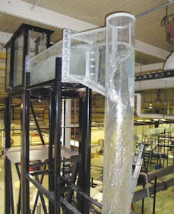
For the DRTC project, he first tested the computer design against simulated operational conditions. Edison then compared simulation data with operational data from a 1:10-scale physical model tested at the University of Iowa's IIHR–Hydroscience & Engineering facility.
Historically, drop structures are designed on paper as adaptations of previous projects then built as scale-models; testing alone can take six months or more. In this accelerated project, AECOM's initial task, beginning in fall 2009, was to choose between two standard concepts: a baffle-plunge style and a tangential vortex version, both designed to slow down and control the often 35-mph storm waters. Hand calculations plus initial CFD analyses determined general structure diameters and components sizes, which AECOM used to evaluate constructability and cost considerations.
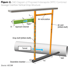
Given the site requirements at CSO 008 and the cost efficiency, the tangential vortex drop structure was chosen. The core element of this design is a vertical tube fed by a tapered approach channel that directs the flow first into an annular jet, then creates a vortex-induced spiral flow pattern down the shaft wall. This controlled descent slows down and safely handles flows that will reach more than 300 million gallons per day (MGD).
The structure itself consists of the approach channel (coming from several existing sewer tunnels); a rectangular transitional taper channel that widens out and delivers the horizontal flow to a vertical drop shaft; the drop shaft itself, which must control the flow downwards to the tunnel; a deaeration chamber that redirects the flow to the horizontal direction and reduces air-entrainment; a vertical air-vent that removes entrained air from the drop and keeps the air core of the dropping fluid open; and a pipe (adit) that connects the deaeration chamber with the storage tunnel chamber (see Fig. 2).
Design and CFD Analysis
Each of the drop structures had to be properly sized to the Indianapolis topology to ensure optimal tangential flow characteristics. In particular, AECOM's CFD evaluation of possible designs had three goals: determine if the site-specific constraint of limiting the combined approach and tapering the channels to short lengths was acceptable and did not create excessively turbulent conditions in the approach; validate that stable flow conditions exist in the taper channel; and assess the flow stability over a range of flow conditions. A logical reference point was the well-known and documented system called the Milwaukee Inline Storage Project.
Edison based the initial design on the Milwaukee drop-structure design, designated H-4, scaled it to the DRTC project dimensions, including a basic drop length of 166 feet, and set up an analysis specifying the volume flow rate, walls, symmetry, and other initial parameters. "What we found with CFD is that Milwaukee wasn't working well for our application, so we used FLOW-3D to come up with a modified design."
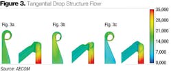
Modifications included using a wider approach channel, wider taper and/or a deeper taper depth. Edison said it was extremely fast to set up each variation in FLOW-3D to go through an optimization process (see Fig. 3). The high level of detail of the simulated results convinced him to add a baffling plate at the base of the drop shaft to improve scour protection and decrease turbulence where the vertical flow transitions to horizontal.
The FLOW-3D output behavior for the ninth design variation, V9, which widened the approach section, exhibited good flow stability at all flow volume levels up through 300 MGD, so AECOM selected it for physical testing and validation starting in February 2010 (see Fig. 4).
Regarding the dimensional parameters determined in V9, Edison said, "We took that design to Iowa and built it based on CFD, and it worked perfectly. The staff (at IIHR) told us this is the first time they've set something up and it just worked." Measured data included water surface elevation within the drop shaft connecting structures, quantification of air entrainment in the adit, and air flow up the vent shaft. Photos of the vortex development as the flow increased showed good rotation and attachment to the shaft wall all the way to the deaeration chamber.
AECOM completed its work on the DRTC in July 2010. In March 2013, excavation began on the 18-foot-diameter tunnel, and all three CSO drop structures (with the other two designed by CFD only) are now under construction.
In Edison's opinion, civil engineering has been slow to adopt CFD. For proof, he described what he saw on his first trip to the IIHR facility -- the so-called "graveyard" of old tangential vortex models. "They were dismantled and rebuilt because they worked poorly, and IIHR had to redo them," he said. Edison, however, is sold on the use of simulation for hydraulic designs.
About the Author: Pamela J. Waterman is an engineer and technical writer in Phoenix, Ariz.
