The treatment of sludge is one of the more demanding applications in the sector. As a result, poor performing pumping systems can often result from underestimating this substance and not considering the special requirements. Roman Gabryjonczyk provides advice on designing a suitable piping system to pump sludge and reduce head loss.
Sludge transportation is the most challenging pumping application in a wastewater treatment plant. Why? As a 'non-Newtonian liquid' sludge exhibits a non-constant viscosity that varies with both applied stress and time under stress. In other words, one sludge type that is thick or highly viscous under tranquil conditions can be caused to flow when shaken, agitated or stressed. Therefore each individual sludge treatment application should be carefully examined before designing a sludge transportation system.
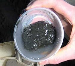
As well as containing potential clogging matter such as large solids, rags and fibres, sludge contains grit and other abrasive matter. Sludge is also a 'non-homogenous' liquid, meaning the liquid and solids can often separate making it even more challenging to deal with.
Furthermore, the rheology of sludge will also depend on the length and shape of fibres, the size and strength of solids in the sludge, its granularity, pH-value, electrical charge of the solids and the temperature of the liquid.
Since the volume of collected sludge impacts the cost of its handling and transportation, one of the goals of sludge collection is to minimise the volume of water in the sludge liquid. In order to intensify the separation of liquids and solids, sewage water or sludge can undergo a chemical treatment or a number of different mechanical processes.
Positive Displacement versus Centrifugal pumps
Selecting pumps for trouble-free operation is a primary concern for wastewater treatment plant operators. Until relatively recently, Positive Displacement (PD) pumps with progressive cavity (PC) and lobe rotor pumps have dominated among the type of pumps used for sludge transportation.
PD pumps popularity is due to the fact that they produce the same flow at a given speed no matter what the discharge pressure and therefore do not require a very accurate assessment of head loss in pipes.
Alternatively, special centrifugal pumps are very effective for sludge applications where dry solids content is below 7-8%. In many of these applications centrifugal pumps deliver better overall economy. Nevertheless it is important to emphasise that both technologies have a raison d'etre in these applications. However, using centrifugal pumps in demanding sludge transportation systems requires a number of actions not necessary, or not as critical, when using PD pumps.
Calculating Head Loss
One of the most important assessments to carry through is a rational estimation of the head losses in the piping system. Careful analysis of performance variation is necessary to accurately ascertain the impact that the slope of centrifugal pumps' performance curves and sludge property variations, have on the treatment of the sludge.
As transport often occurs intermittently in a wastewater treatment plant, any differences in pump performance resulting from changing characteristics of the sludge during operation can be often handled without detrimental effect to the treatment processes. When dealing with sludge it is simply not possible to accurately calculate dynamic head loss as can be done in case of water or wastewater.
There are two main methods for estimating the head loss in a pipe system when working with sludge. One is to use sludge rheological data in order to assess the shear stress value on the pipe wall. The other is to try to find an appropriate definition of the 'Reynolds number' for the sludge in question, followed by calculating the friction factor from the Moody's diagram.
A carefully designed piping system will be rewarded with a better overall performance and a problem-free sludge treatment operation. There are plenty of poor performing sludge pumping systems in wastewater treatment plants all over the world. Quite often the systems have been designed for water or wastewater without considering the special requirements that sludge demands. A thoughtfully designed piping system with an in-depth understanding of the type of sludge involved will contribute very positively to the smooth operation of the sludge pumping system.
Tips for Reducing Head Loss
In order to design an optimal pumping system, assessment of anticipated system head loss is required. Excessive head loss will always result in an unnecessary cost burden for operators. Therefore all available measures to reduce the loss should be undertaken:
1. Keep flow velocity around the optimum value of 1 m/s. Increased velocity in general, increases head loss. On the other hand, too low velocity increases the sedimentation of particles and investment costs.
2. Consider changing old pipes into new. Old pipes can suffer from a deposit of sludge particles on the inner wall of the pipes which leads to diameter constriction and varying roughness of the surface, both of which affect head loss. Therefore, it is always recommended to compare the results from old and new pipes in order to ascertain whether or not pipe replacement would be a wise investment.
3. Keep the pipe length short. The head loss in a pipe is also directly proportional to the length of pipe. Therefore, keeping the pipe work as straight and short as possible is wise.
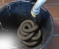
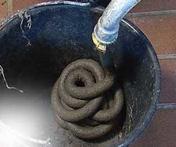
4. The pipe diameter is decisive for system head loss. It is advisable to keep the piping the same diameter throughout, if at all possible, in order to avoid blockages and maintain the optimum velocity (i.e. 1 m/s). Remember - using pipes with a diameter that is wider than the largest anticipated particles does not always prevent a blockage! Large rope-like solids may build up as a result of the intertwining of fibers and hair caused by rotating sludge pumps and mixers. The minimum that is recommended is 100mm. When dealing with unscreened sludge, incorporating grinding equipment into the system should be considered.
5. Pipe construction material will influence the head loss through the material structure which affects the relative roughness. The roughness matters only when sludge exhibits turbulent flow pattern.
6. Fittings can contribute significantly to the total head loss; often as much as pipe friction. Therefore the shape, size and the number of fittings should be carefully chosen. For example, long bends are recommended i.e. bends with a ratio between its curvature radius and pipe diameter larger or equal to 1.5.
7. Changes in the sludge rheology may cause a shift from laminar to turbulent regime or vice versa. This will affect head loss. Other sludge properties such as TS content, polymers and origin can also affect the rheology.
8. 'Start-up head' refers to the threshold which has to be overcome to initiate any flow in the piping system. The start-up head is influenced by sludge rheology via yield stress. This needs to be considered for TS=>4% in general.
Ensuring Sooth Operations and Using Valves
In addition to assessing head loss in the pipe system, there are two key issues when designing a system for sludge pumping; a) to get sludge into the pump and b) to avoid gas blockage. The experience of other wastewater treatment plants in the area may be extremely valid; it is important to talk with colleagues from plants in the neighbourhood.
If valves are necessary, it is always advisable to use wedge style gate valves in order to minimize the risk of clogging. Placing them as close to the pump as possible will avoid spillage. The suction pipe of the system should be designed in a manner that encourages the sludge to flow spontaneously to the pump inlet.
Avoiding Gas Build Up
The system should be designed so that sludge is not trapped or blocked between closed valves. Biologically driven gas production may raise the pressure to the system's limit. Therefore, these parts of the system should be flushed before closing valves. Pressure relief valves or bursting discs can also be used to protect the system.
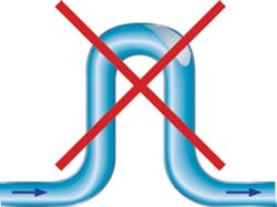
A treatment work consists of a grid of pipes crossing each other - make sure that the sludge piping system will not be a roller coaster ride, with high points where gas accumulates, particularly as a result of intermittent pumping. The gas pockets form a constriction to the flow and may create additional head loss, or in a worst case scenario, a pipe blockage.
Pipe Diameter, Sludge Dilution and Flushing of Pipes
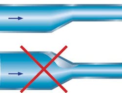
As previously mentioned the diameter of pipe should be kept constant through the whole pipe length if possible. However if a taper is necessary use a flat top instead concentric tapers. This will avoid gas pockets which constrain the pipe's throughlet, increasing head loss and in extreme cases, causing pipe blockage.
Furthermore, examine whether the piping system should be equipped with the means for sludge dilution or pipe flushing. Pay attention that dilution will work effectively - the sludge flow needs to be somewhat turbulent to allow the dilution liquid to mix well with the sludge. Provision for flushing of the pipes with either cold or hot water may be necessary to prevent a build-up of deposits on the pipe walls, especially if the system is operated intermittently. Hot water is often the only way to clean pipes clogged with fatty compounds.
Head Loss Reducing Techniques
When pumping dewatered sludge through pipes longer than 20 metres it might be justified to install head loss reducing equipment. Two common methods of reducing friction loss are available. One deploys air injection into the sludge flow, which form distinct air slugs that travel, nearly frictionless, in between consecutive sludge plugs. Up to 80% head loss reduction is attainable during optimal condition. The injection takes place around one metre from the pump discharge.
The other method is injection of lubricating polymer film, 25-35l/hr depending on pipe diameter, between the sludge and the pipe wall. Due to mixing that takes place between film and sludge the film will gradually be absorbed by the sludge. Injection points should therefore be repeated every 20 metres along the pipe. This method may reduce the head loss dramatically - by up to 80-90%.
Maximising Gravity
This suggests pump location to be as close the sludge source as possible and below, or at the bottom level, of the tank. If the pump operates intermittently, provision to increase velocity once or twice a day to flush the pipes or a means of cleaning the pipe with water from time to time should be incorporated into the system.
In summary, considering the following when designing a sludge pumping system for a wastewater treatment plant will support a smooth, trouble-free operation:
• Sludge origin, dry solids content and if possible, rheology of sludge
• Rationally handled head loss
• Select the most appropriate pump technology for the specific sludge treatment application
• Issues most often arise as a result of problems in the piping system rather than issues with the pumps themselves
• Employing expert advice at the outset can often prevent expensive problems down the line.
Author's note: Roman Gabryjonczyk is senior application specialist with Xylem. He has over 30 years of experience in different fields of pumping applications. For the past eight years Roman has focussed on pumping in wastewater treatment plants, in particular sludge pumping, examining the different technologies used as well as designing and developing piping and pumping systems.
