by Steve McKelvie
Cast iron pipes have been used in water distribution systems for many centuries. The first official record of cast iron installation was in 1455 in Siegerland, Germany. In 1664, French King Louis XIV constructed a 24 km cast iron pipe from a pumping station to Versailles. This pipe is still in service. Cast iron pipe was used in the U.S. as early as 1817, when it was installed in the Philadelphia water system.
The conservative designs and manufacturing processes used long ago have resulted in pipe that has lasted beyond what we today consider to be its design life, and it can still be expected to provide many more years of cost-effective service. Many old cast iron pipes are good candidates for rehabilitation. For such rehabilitations to be successful, however, we need to understand some of the history of cast iron pipes, the standards they were designed to and how they were manufactured.
Design standards for cast iron pipe date back to the late 1800s in the United States, with the earliest record of an American Water Works Association (AWWA) standard being 1890. In 1902, the New England Water Works Association (NEWWA) adopted a more detailed standard entitled “Standard Specification for Cast Iron Pipe and Special Castings,” which reflected design practice in use at the time.
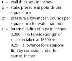
Pipe wall thickness at that time was determined using the following formula:
null
where:
null
There were several reasons for the thick pipe walls. Design procedures used then were still being developed. A preliminary report on NEWWA’s 1902 standard stated, “The static head or pressure can be closely estimated, but water hammer, the effect of traffic over pipe, settlement under it, tuberculation within it (localized corrosion resulting in nodular formations of corrosive products), electrolysis outside of it, and age everywhere can, with present knowledge, be given no mathematical value.”
The Marston Equation, which permitted the identification of earth loads on pipe and was perhaps the most important design procedure for the analysis of rigid pipes, was not developed until 1913. Spangler’s work in developing load factors for rigid pipes was not published until 1933.
Fortunately today these factors- conservative design and conservative manufacture - have resulted in a pipe that has lasted beyond its originally anticipated design life.
Suitability for Rehabilitation
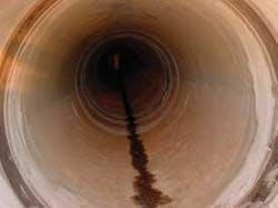
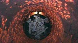
Both the external and internal conditions of the pipe must be assessed to determine the suitability of a metallic water pipe for rehabilitation. Corrosion may attack a pipe surface in an overall way, reducing the wall thickness of the pipe generally, or the attacks may be of a more localized nature. Localized corrosion attacks are more difficult to confirm. On the other hand, the corrosion products of cast iron pipe are adherent and help protect the metal beneath.
The appreciable amount of graphite, about 10 percent by volume, together with relatively inert iron oxides and phosphates, causes gray cast iron to be somewhat corrosion resistant. This durability against external corrosion forces, together with the thicker walls, makes such older cast iron pipes good candidates for rehabilitation.
Structural Analysis
Cast iron pipe is considered to be a rigid pipe for the purposes of design and analysis. Using a combined loading method, we can establish separately the maximum internal allowable pressure and the maximum allowable external loading, then combine these two values for pipe assessment.
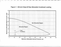
A typical combined loading curve that has been prepared for cast iron pipe shows that as the external load is increased the maximum allowable internal pressure must be reduced. The security of the pipe cannot be certain if the combined load exceeds its maximum capacity. The acceptable factor of safety should be developed with input from the owner.
The following procedure will help provide the owner with information needed to understand the condition of the pipe and to make judgments concerning the rehabilitation needs of the pipe at the level of safety that the owner finds acceptable. The primary steps involved are as follows.
Pipe Width Allowances. Two allowances are used to address actual conditions in the design of iron pipes:
- A corrosion allowance of 2 mm (0.08 inches)
- A casting allowance, which is applied because the manufacture of cast iron products is not a precise operation. For 1.2-m (48-inch)-diameter pipe, NEWWA identified a casting allowance of 2 mm (0.08 inches).
The result of these two allowances is that the net wall thickness allocated to withstand design loads is the standard wall thickness less 4 mm (0.16 inches).
Internal Pressure. The net wall thickness needed to withstand the internal pressure can be determined using the following equation:
where:
t = required net wall thickness, inches
p = internal pressure, psi
D = outside diameter, inches
S = stress in pipe wall, psi.
External Pressure. The effects of the external loads on the pipe can be determined using the following formula:
null
where:
MR = Modulus of rupture or stress, psi
W = total external load, lb/ft.
D = outside diameter, inches.
t = wall thickness, inches.
By setting the maximum allowable modulus of rupture or ultimate stress, the maximum allowable external load that can be applied to the pipe can be established. This load would be equivalent to the three-edge bearing strength of the pipe.
Combined Effects. The combined effects of the internal and external loads can be determined using the Schlick equation, which was based on cast iron pipe research done in the 1930s.
w = W [(P - p)/P)] ½
where:
w = three-edge bearing load at failure under combined internal and external
loading, lb/ft
W = three-edge bearing strength of the pipe with no internal pressure, lb/ft
P = burst strength of the pipe with no external load, lb/in2
p = internal pipe pressure at failure under combined internal and external loading, lb/in2
Factors of Safety. The three pressures that must be assessed when considering internal design pressure are normal operating pressure, transient pressures and test pressures. The uncertainty associated with these pressures is not the same, so the appropriate factors of safety for each of these values may not be the same.
- Normal operating pressure. This is the pressure difference between the normal hydraulic grade line of the system and the elevation of the pipe. This value can be determined with reasonable certainty; thus, its factor of safety could be 1.25.
- Internal transient pressures. Also referred to as water hammer pressures, these pressures are less well defined, and the appropriate factor of safety against this condition could be 2.0.
- Test pressure. This is applied under controlled conditions to verify the design and installation of the pipe. The factor of safety applied could be 1.25 to 1.50.
Calculation Procedures. The maximum internal pressure can be calculated using Equation 2. The designer should consider the value of the wall stress used in that equation. If a value of 16,500 psi is used, then the resultant internal pressure would be the ultimate capacity of the pipe assuming that the cast iron still retains the same tensile strength that it had when it was manufactured. It would be prudent, however, to use a current tensile stress value of less than 16,500 psi. Metallurgical testing of the cast iron would be helpful in establishing an appropriate value.
In a similar manner, the maximum external load that can be carried by the pipe can be calculated using Equation 3. The Modulus of Rupture for 100-year-old, 1.2-m (48-inch)-diameter cast iron pipe in Boston was determined by Talbot Strip tests to be 29,000 psi. The result of Equation 3 is the maximum external three-edge bearing capacity of the pipe. This is equivalent to having a safety factor of 1.0.
Using the results of Equations 2 and 3, the ultimate combined load carrying capacity of the pipe can be determined by using Equation 4. This curve is equivalent to a safety factor of 1.0.
Loading Conditions. The next phase of the evaluation is to identify the loading conditions that the pipe will experience. The combinations of internal pressure and external loading should be plotted on the combined loading curve. The distance that the plotted points are from the ultimate combined loading curve represents the factor of safety against pipe failure under that condition. Each of the loading conditions should be evaluated and judgment used about suitability of the resultant factor of safety.
Case In Point
The Massachusetts Water Resources Authority supplies water to the area in and around Boston. Some portions of the piping system consist of cast iron pipe installed in the early part of the 20th century. Section 23 of the system delivers water at the Southern High Hydraulic Grade Line of 272 feet. The pipe is a 36-inch diameter Class B pipe.
This pipe had an initial wall thickness of 1.15 inches. For this pipe, in place, the minimum cover is 2 feet and the maximum cover is 8 feet. The minimum centerline elevation is approximately 135.6 feet. Therefore the maximum static pressure is 136 feet or 59 psi.
The maximum external load carrying capacity was calculated using Equations 3 and 4. This allowable external load was converted to an equivalent depth of cover including an H20 live load. The results of this analysis are shown on Figure 1.
As can be seen from Figure 1, the field conditions are well under the design curve or in the allowable region. With an internal pressure of 59 psi the allowable depth of cover is less than 23 feet but more than 1 foot. The graph also shows given the Field Conditions the maximum allowable internal pressure is considerably higher than the maximum static pressure. This provides capacity to withstand any expected internal transient pressures. The conclusion of this analysis was that this pipe is a good candidate for rehabilitation.
Conclusion
Experience over many years has shown that the life span of cast iron pipe can be extended well beyond its original design expectations. By following the formulas cited above, owners and engineers can determine with confidence the ability of their pipe to withstand additional years of service or be a prime candidate for a cost effective rehabilitation program.
About the Author:
Steve McKelvie is a Senior Supervising Engineer in the Boston, MA, office of PB. He has been involved in pipe and pipeline design issues for more than 30 years and is active in writing pipe design standards for the American Waters Works Association. McKelvie is currently working on a cast iron pipe rehabilitation project for the Massachusetts Water Resources Authority.


