by Norman Noe
A water tank acts as a relief valve on your water system. If the pressure in the system increases past its design capacity, it increases the water level in the water tank past the high water level. The water then spills into the weir box or overflow pipe inside the tank, and the excess water then drains outside the tank. This is usually a fail-safe system which stops excessive amounts of pressure from building up in the underground water lines.
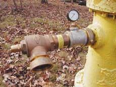
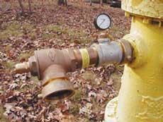
On a single-tank water system, when the tank is taken out of service due to a tank freeze up, or inspection/maintenance, it usually must be isolated from the system. Relief valves are placed on fire hydrants to replace the tank and relieve any excess water pressure.
How these are installed can be critical to their success, and the number of valves to be installed and their positioning in the water system will vary from one system to another. However, two relief valves are generally better than one. If only one valve is installed problems can arise. A single valve could malfunction, it can be vandalized, or a good Samaritan could mistake the blow-off of the valve for a problem and turn off the hydrant. These problems have occurred in the past, resulting in excessive pressure and leaks in the system.
The following system has worked for us in the past. First, do not make any changes in your system before you install the relief valves. Leave the pumps on. This is a key element. Then, the gate valve that isolates the water tank should be located and a turn key installed. The relief valves are then installed on the fire hydrants, making sure that the location has good drainage for the blow-off water. Do not allow this water to endanger the public or property, such as wetting or icing down a sidewalk or street, or flowing onto a garden.
If the relief valves have pressure gauges don't put too much faith in them. Remove the end cap from the relief valve and loosen the lock nut from the adjuster. Slowly open the fire hydrant all the way. Make sure the spring inside the relief valve isn't stuck. Open and close the spring manually to be sure. This can easily be done with the end of a crescent wrench.
Now adjust the pressure adjuster on the end of the valve from almost open to almost closed. Do this several times. This "exercises" the spring in the valve. By now you should be good and wet. Adjust the pressure adjuster to its closed position, shutting down the water flow. Now slowly open the adjuster. You will first hear a "hissing" sound as air escapes the valve.
Continue opening the adjuster until the water just starts "spitting" out of the valve. Stop at this point and tighten the lock nut on the pressure adjuster and replace the end cap. No matter what the pressure gauge on the valve says, the relief valve should now be set just a few pounds below the water pressure at the hydrant.
Repeat this procedure with any other relief valves to be installed. Loosen the nuts of the tank's removable manhead, and close the valve that isolates the tank from the water system. The water tank may now be drained from the tank's drain valve or drain hydrant. Again, observe proper drainage and public safety.
After the tank is drained, immediately remove the tank's manhead. Usually the pumps are then set on manual/hand, and only pump the minimum volume of water into the system that is required. The pressure in the system should be closely monitored and the relief valves should be checked and adjusted if necessary.
About the Author:
Norman Noe is president of Norman Noe Co. Inc., a third-party water tank inspection and consulting firm that also supplies relief valves to the water industry. He is a NACE Certified International Coating Inspector and has served on AWWA's Steel Tank Manual Task force. He also serves on many NACE and SSPC technical committees. He can be reached at 317-933-2274. WWCircle No. 309 on Reader Service Card


