Expecting to dismantle and replace its entire Puncheon Run Pumping Station including the pumps, controls and wiring, the City of Dover needed a temporary pumping system capable of handling flows ranging from 1,875 gpm at 168 feet of head to 3,000 gpm at 120 feet of head. In addition to these drastically varying flow requirements, the project offered the up-front challenge of limited space availability.
With a 30-foot by 30-foot area for pump placement and only slightly more room for system assembly, the lack of space made it difficult to set up the job while leaving enough room for the contractor to move equipment and materials in and out of the building, and added to the complexity of identifying pumps that could match the flow requirements and the space restrictions.
The project was awarded to C&D Contractors Inc., who worked in cooperation with Godwin Pumps.
“This was not your basic bypass,” said Godwin Sales Engineer Dale Brackin. “When I looked at the requirements for the job, I brainstormed with our chief engineer, my sales manager and the contractor, C&D Contractors.”
This team has a combined 50+ years of experience in the pumping business. They pooled that experience with the technological input of another Godwin Pumps engineer to create the winning proposal.
Plan of Attack
“There were so many things to consider, but the starting point remains finding a pump and controls to meet the flow requirements of the system,” said Godwin Chief Engineer Mike Ramos.
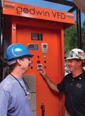
Godwin’s CD160M Dri-Prime® pumps were selected for the project. Available with diesel engines or electric motors, the pumps are rated for 1,900 gpm at 260 feet of head. For the Puncheon Run Station, the company delivered two 150 hp electric drive pumps with 200 hp variable frequency drives (VFDs) incorporating level transducers and programmable logic controllers (PLCs) to serve as the primary and lag pumps. One Critically Silenced 147 hp CD160M diesel pump with a Godwin PrimeGuard Controller and level transducer served as a backup. One standard 147 hp diesel pump with a PrimeGuard Controller, level transducer and hard-wired Chatter Box Auto Dialer supported the entire system in the event of major storm surges or power outages.
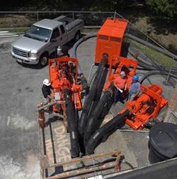
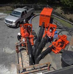
At roughly 11.5 feet long and 4.5 feet wide, the four CD160M pumps were compact enough to meet the space restrictions. However, when combined with all of the other equipment the job would need and the space available to piece it together, the team quickly met its next challenge.
Some Assembly Required
Along with the four pumps, the project team determined that the Puncheon Run bypass would require four, 20-foot lengths of 8-inch flanged discharge hose; four, 10-inch high density polyethylene (HDPE) dip tubes with 10-inch flanges; and roughly 150-feet of 18-inch HDPE pipe, adapters and elbows that - in addition to check valves, a discharge manifold, combo vents, a flanged reducer and ball valve - all needed to be fabricated and/or assembled on-site.
Working with C&D Contractors, Godwin’s fusion technicians assembled the HDPE sections and connections in stages, starting from the discharge point (an emergency force main connection), and crane-lifted them over the roughly 20-foot-high pumping station building. The team fused the approximately 100-foot length of HDPE discharge pipe, tying it into the single, 18-inch outlet of the discharge manifold. On the inlet side of the manifold, they connected a check valve to each of the four, 8-inch, 20-foot-long discharge hoses that tied directly into each pump.
In the final stages of assembly, the four pumps and their controllers were brought in and connected. When it came to space limitations, the suction point was no exception. The only pickup spot for flow was a large diameter manhole located just before the pump station wet well. The manhole became home to the four, 10-inch HDPE dip tubes, four level transducers and left just enough room to install a sewer plug. The entire, assembled system provided adequate space for the contractors to move equipment in and out through the pumping station door.
Control System
The plan for approaching the flow conditions was simple: the first (lead) electric drive and the second (lag) electric pump were equipped with VFDs that incorporated a level transducer and PLC that allowed the VFDs to work together. Using these controls, Godwin engineers could identify and program system variables that could vary the pump speed to keep up with the influent, start and stop pumps as demand required, and alternate lead and lag control between the two pumps to ensure that the entire system was in proper working order and that the pumps experienced an equal amount of run time/wear exposure to prolong performance.
The VFDs worked only to deliver the flow necessary for system conditions, instead of starting and stopping continuously as with a float-type system. This approach lessens the wear and tear on the pump and decreases the power surges and costs associated with the peak demand on the pump.
Likewise, the level transducers sense the pressure as the water rises and send a signal to the VFD to speed or slow down the motor. The challenge with using a level transducer in a manhole is the turbulence in the water. Godwin inserted a perforated tube into the manhole, creating a stilling well for the transducers. In addition to protecting the transducers from the debris in the manhole, the tube displaced the turbulence, rendering it undetectable. This created a cleaner signal, thereby avoiding rapid cycling. The level transducers were also equipped with a level signal selector switch that took the average of both transducers or would switch from one transducer to another, if a signal went bad.
Pumping on a force main requires a variable head condition that is proportional to flow. When only one pump is running, the discharge head will be much lower than with all three pumps in operation. Excessive use of a single pump running at full speed with no head could potentially lead to cavitation and needless damage. The VFDs each had a PLC that was programmed to only allow the single pump operation to run up to a lower maximum speed unless more than one pump was required to handle the flow.
The two diesel pumps were each equipped with PrimeGuard Controllers. These diesel-driven pumps were required as backups in the Puncheon Run bypass, and were controlled independent of the electric pumps, making them self-sufficient. In an effort to exercise the diesel pumps on a routine basis to ensure system functionality for emergency conditions, the first diesel backup (P3) would start up once a week. The system backup pump (P4) would also start once weekly, sending an alarm signal through its Auto Dialer to verify that the backup system functioned properly.


