by Allan Budris
As noted in the last column, one of the basic traits that distinguishes the best-of-class from the retroactive-fix-up pump users (whose associated pump costs are normally much higher) is: Best-of-class users evaluate the total pumping system, and not just the pump, in order to minimize energy usage. There is normally much more potential in the proper application of a pump and the system design, then just the pump efficiency alone.
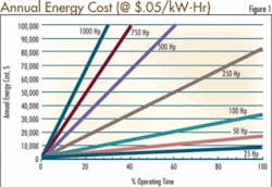
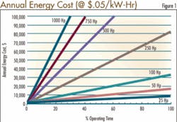
Pumping systems account for nearly 20% of the world’s electrical energy demand, and 25-50% of the energy usage in certain municipal applications. Further, many pump installations are operating at much less than optimum efficiencies, which represents fertile ground for sizable energy savings. Figure 1 shows the sizable annual pump energy costs, based on motor size and percent operating time, for an energy cost of $.05/kW-hr. Typical energy costs are generally higher. Based on the experience at one industrial plant, energy savings as high as 60% of current usage (with an average savings over 30%) are possible.
Proper pumping system design and operation are the most important elements in minimizing energy and life cycle costs. Guaranteed or rated pump efficiency is only one component among many, and usually not the most important. There are other, often more meaningful savings to be realized by looking at the entire pump system, including the piping, fittings and valves before and after a pump, as well as the motor and motor driver. Also, pump operation can have a sizable impact on overall energy costs. There can be multiple pumps, motors and drives, and they can be arranged to operate in parallel or in series. Parallel pumps can be operated in a variety of combinations and flow rates. To minimize energy costs, the most energy-effective pump(s) should be operated at their most energy effective flow rates (which is normally at maximum flow).
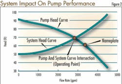
The point at which a pump operates on its performance curve depends on the intersection between the pump head-capacity curve and the system curve (figure 2). Therefore, when planning for energy conservation, the system should be designed, or pumps selected, to force the pumps to operate close to their best efficiency flow-rate. Avoid wasting power by over-sizing pumps. One of the most serious wastes of power involves the traditional practice of over-sizing a pump by selecting design conditions with excessively “conservative” margins in both capacity and total head. Some margin should always be included, mainly to compensate for the wear of internal clearances, which will, in time reduce the effective pump capacity. Traditionally, system designers have piled margin on top of margin “just to be safe”. Some of this margin can definitely be eliminated.
But what of existing installations in which the pump or pumps are oversized and have excessive margins? It is not too late to achieve these savings. It is now possible to establish the true system-head curve even more accurately by running a field performance test once the pump has been installed and operated. Once a reasonable margin has been selected, four choices become available:
1. The existing impeller can be cut down to meet the real service conditions required for the installation.
2. A replacement impeller with the necessary reduced diameter may be ordered from the pump manufacturer. The original impeller is then stored for future use if friction losses are ultimately increased with time or if greater capacities are ever required.
3. If two separate impeller designs are available for the same pump, one with a narrower width, as is sometimes the case, a replacement may be ordered from the pump manufacturer. Such a narrow impeller will have its best efficiency at a lower capacity than the normal-width impeller. Again, the original impeller is put away for possible future use. A new smaller capacity pump may turn out to be an even better alternative.
4. Replace the control valve with a variable frequency (speed) drive VFD. VFDs are ideal for varying flow or head conditions, in systems with relatively low static head. They are of little benefit in systems with constant flow rates and/or high static head. Variable frequency drives, especially larger ones, do have their issues, such as stressing the motor and drive cables with high frequency voltage rises; they can cause harmonic losses in the motor, which can cause the motor to run hotter; they can generate stray motor currents which may require the grounding of the motor bearings; and they can pollute the supply grid with harmonics. However, with careful design and selection, today’s VFDs eliminate most of the harmful affects. On the positive side, VFDs have the potential to offer:
a. Large energy savings, plus they eliminate the control valve (and associated losses), starter and bypass lines.
b. They generate higher supply-side power factors at all loads, unlike a constant-speed motor.
c. They eliminate the inrush current on startup. Soft starting reduces the stress on the motor, pump, coupling and the supply network.
d. They can provide system control logic, fault protection and diagnostics.
Now let us look at the full chain of elements that are involved in the overall energy flow in a pumping system. Each element and /or interface adds some inefficiency. The goal should be to maximize the overall efficiency, which is the product of the efficiency of each of the system energy transfer or conversion devices.
- Electric utility feeder lines (higher voltages and power factors reduce these losses).
- Transformer
- Motor breaker/starter
- Adjustable-speed/frequency drive VFDs
- Motor (available in various efficiency ratings)
- Coupling
- Pump (note that this is only one of the elements)
- Fluid system (includes control valves and piping which determine the friction loss)
- Ultimate goal (flow-rate at a given static head increase).
About the Author:
Allan R. Budris, P.E., is an independent consulting engineer who specializes in training, failure analysis, troubleshooting, reliability, efficiency audits and litigation support on pumps and pumping systems. With offices in Washington, NJ, he can be contacted via e-mail at [email protected].
