Simulation of aerated grit chamber saves US$ 200,000/year in power costs
Carollo Engineers used computational fluid dynamics (CFD) to develop a new design that made it possible to reduce the aeration rate by 30% while improving particle removal efficiency.
Computer simulation helped engineers find a more efficient geometry for an aerated grit chamber used for a pre-treatment process in a large wastewater plant that reduced power costs by US$ 200,000 per year. The chamber is designed to handle 88 million gallons per day (mgd).
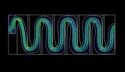
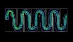
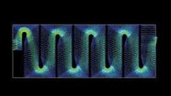
Recognising that the geometry of the unit can affect operating costs, engineers from the US consultancy Carollo Engineers used computational fluid dynamics (CFD) to evaluate a number of designs prior to construction. Simulation showed that “classic tallwall” of the initial concept design of the chamber drove the flow deeper into a hopper at the base of the chamber, used to collect particulate matter. The result was that the flow dislodged particles that had already settled. Using CDF, they developed a new design with shorter and narrower walls that made it possible to reduce the aeration rate by 30% while improving particle removal efficiency. The design was simulated over a wide range of liquid and gas flow rates and was determined to perform better than the original design.
Grit chamber design issues
Carollo was contracted to help design and build the aerated grit chamber as part of an expansion of the Clark County Sanitation District Central Plant in Nevada. Used in the pre-treatment area of the plant, these chambers remove sand, shells and other gritty material from the wastewater. They are one of the first stages in the plant, following only a bar screen that is designed to take out large objects. The grit chamber is typically created by building internal walls below the surface of the water in a holding tank. The flow stream can be generated in several ways. One technique is to swirl the water with a mixer. Another approach, which was used in this project, is to aerate or pump compressed air into the chamber. The air bubbles create circulation patterns in the water that the grid particles are usually unable to follow.
The greatest design challenge in this type of grit chamber is configuring the geometry, dimensions and air flow rate to optimise the settling process. The most critical variables are the size and height of the chamber, the size and geometry of the hopper, and the volume of air that is pumped into the chamber. If the walls are too low, water might be forced into the hopper where it would dislodge particles. If the walls are too high, splashing can occur that has the potential to release odours into the environment. If too much air is injected into the grit chamber, the water will spin so fast that the particles won’t have a chance to settle. If too little air is injected, the water will never attain the velocity needed to promote settling. Another concern is that the tank be able to work efficiently at the full range of operating flow rates that the plant experiences.
Build-and-test to simulate
In the past, the only method engineers had to determine the effectiveness of a proposed design was to build a scale model of the grit chamber and perform experiments. This approach is expensive and time-consuming and often provides inaccurate results in many cases because of scaling factors. In order to overcome this problem, Carollo engineers have begun using CFD software to simulate the flow of water and air through the grit basin. A CFD analysis provides values of fluid velocity, pressure drop and other relevant variables throughout the solution domain for problems with complex geometries and boundary conditions. It can also be used to track the trajectories of a particulate or gas (bubble) phase. As part of the analysis, an engineer may change the geometry or the boundary conditions, such as inlet velocity, and view the effect on fluid flow patterns or bubble trajectories throughout the system. CFD can also provide detailed parametric studies that can significantly reduce the amount of experimental work necessary to develop prototype equipment and thus reduce design cycle times and costs.
Carollo engineers selected FIDAP CFD software from Fluent Inc., based in Lebanon, New Hampshire, as one of their primary CFD tools. FIDAP is an integrated fluid modelling software suite with complete capabilities for every step of fluid flow simulation: model building, mesh generation, data input, solving and post-processing. Aerated grit chambers are very challenging from a modelling standpoint because of the difficulty in capturing the interactions between full-scale performance and CFD simulation has shown that FIDAP provides results within + /- 5% accuracy.
Optimal design
Carollo engineers used FIDAP to create a quasi-3D finite element model of their initial concept design with about 300,000 elements. They performed a two-phase analysis of the aerated system to study the motion of water and bubbles. They used another CFD software package, FLUENT, from the same manufacturer, to model the inlet in three dimensions and used the results of this model to apply boundary conditions to the previous model. The Lagrangian particle-tracking model was used to simulate the gas phase. Turbulence in the system was incorporated using the renormalised group (RNG) model. The simulation results showed significant problems with the initial concept design. The tall wall in the design drove the flow deep into the hopper, scouring out particles that had already settled. Another problem was that fairly rapid flows were going over the top of the chamber walls. These flows were fast enough that they could easily cause splashing that would tend to release gases from the wastewater.
To overcome these problems, engineers tried a number of chamber configurations and flow rates with the goal of achieving the best particle removal at the lowest airflow. Once they had zeroed in on a promising approach, they used parametric analysis to systematically modify key dimensions and angles to optimise the design. The ideal design turned out to be a significant departure from those that had been developed in the past using trial and error methods. In the normal approach, the wall that forms the chamber starts at the bottom of the holding tank, but Carollo engineers found that they achieved better results with the wall starting at a distance above the bottom of the tank. In addition, they made the chamber smaller than the normal width and depth. The hopper is also different from the normal upside pyramid. Instead, the wall of the hopper is vertical on one side and has a very steep slope on the other side. This change not only improves performance, but also reduced construction costs, since less than the normal amount of excavation was required.
Operating costs reduced
These improvements resulted in a 30% reduction in airflow requirements, saving about US$ 200,000 per year in power costs. The performance of the new design, measured in terms of solids carryover to the next stage, is actually better than the traditional approach since the lower velocity of flow removes a large size range of particles. The new design provides better solids removal because water flows in a plug flow manner so that all energy is used for mixing the fluid rather than being wasted in eddies.
This project example demonstrates the way in which computer simulation can dramatically improve the performance of wastewater facilities. Computer simulation typically costs about 10% as much as building a physical model, yet provides far more freedom to evaluate various alternative designs. Improving the efficiency of the aerated grit chamber, in this example, dramatically reduced power and capital expenses while avoiding problems with varying flow rates.
Author’s Note
Sanjay Reddy, P.E. is an associate engineer at Carollo Engineers, located in Walnut Creek, California, USA. The company specialises in the planning, design and construction management of water and wastewater projects for public agencies, municipalities, and industry. Carollo designed the 624-mgd Alfred Merrit Smith Water Treatment Facility in Las Vegas, Nevada, which is the largest direct filtration plant in the USA. For more information on the Fluent CFD software, visit the website: www.fluent.com


