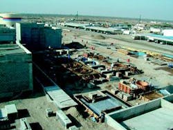
Barka power and desalination project on fast track
By: Corrado Sommariva and Ramachandran Venkatesh
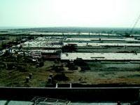
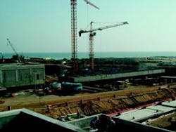
Oman's first privately-financed power and desalination project, fast-tracked to meet short-term demands, will be completed on-time by November 2002. The US$ 315-million Barka plant, situated on the Batinah Coast, is part of a government strategy to improve efficiency and help diversify the economy by privatising its electricity and water sectors.
The Sultanate of Oman's Ministry of Housing, Electricity and Water (MHEW) awarded the build-own-operate (BOO) project to the US company AES, which appointed the Japanese company Hitachi Zosen and Enel-power acting as EPC contractors for the desalination and power facilities, respectively.
The Barka project will be developed in two separate phases. The first phase, now under development, will result in a net power output of 427.36 mW and 6.6 million Imperial gallons of water per day (migd). Two gas turbine generators of a gross power output of 117.36 mW plus one steam turbine generator of 222 mW-rated output will generate power in the first phase.
The steam downstream of the steam turbine generators is passed to the desalination yard where three multi-stage flash desalination plants will each provide a capacity of 6.6 migd. The V94.2 model gas turbines provided by Siemens of Germany are designed for duel fuel-firing, using natural gas and oil. The system is equipped with downstream heat recovery steam generators that have a provision for supplementary firing to cater for operational flexibility.
The back pressure steam turbine provides for total steam bypass and is fed with steam having the following parameters: flow of 121 kg/sec, 77 bar pressure and 541 °C. Each evaporator can reach a performance ratio of 7.7 in fouled conditions. Auxiliary equipment and seawater intake are designed for future project extension.
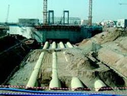
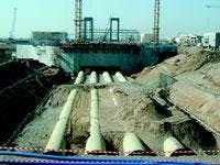
The intake structures will be of a velocity cap type set at five metres below the Lowest Astronomical Tide (LAT) 1,200 metres into the sea. A series of 2.2-m-diameter intake pipes, buried in the sea bed with a minimum cover of 2.5 m, will be installed between the intakes and on-shore seawater pump house - a monolithic concrete structure incorporating a stilling basin, six bar screens, six motorised band screens, a pump bay and 16 pump chambers.
Each main seawater supply pump has its own pump chamber, except for firefighting and auxiliary pumps fed via a common forebay. Each chamber can be isolated by stop gates for maintenance to allow the dewatering of each individual sump. Pumps bays are sized with a nominal approach velocity of not more than 0.25 m/s in accordance to Hydraulic Institute standards. The Hydraulic Institute is located in Parsippany, New Jersey, USA.
The stilling bay will be divided into two separate bays for Phase 1 (427 mW power and 20 migd desalination plants) and Phase 2, in which the plants will be expanded.
The outfall facilities include 2.5-metres-diameter sub-sea discharge pipelines, each 700-metres-long and similar in design to the intake system, and a discharge sump. An electrolytic chlorination plant using seawater as raw make-up feedstock will also be constructed to inhibit biological growth and fouling of the entire seawater systems.
Design review
In March 2002, the UK consultancy Mott MacDonald completed a design review of the facilities shared by the power and desalination plants, including the seawater intake and distribution electrochlorination plant. The consultants also reviewed the hydraulics of the seawater intake and outfall structures and conducted a numerical recirculation study of the intake and outfall system.
Defining seawater hydraulics proved to be one of the most interesting and delicate aspects of the design review. UK-based HR Wallingford carried out the intake sump model study for a total flow of 133,880 m3/hr, appropriate for Phase 1 and 2. A performance test of the pumping station was carried out using a model constructed to a scale of 1:12.5, and was operated according to Froudian scale criteria.
Froudian scale was selected as it has been generally found that vortex motions could be more correctly reproduced in a Froudian-operated model when specific limitations on Reynolds and Weber Numbers are maintained. Many research projects conducted in models based on Froud numbers have led to more reliable results when compared to the prototype.
The study demonstrated that minor modifications in the pumping station minimised the water jets from the intake pipes and produce more uniform flow distribution at the entrance of the screen chamber. This change should inhibit strong subsurface vortex formations observed during the test.
Baffles were added to reduce the jet effect and the velocity at the inlet was reduced to 0.5 m/sec. The velocity at the screen section was reduced to 1 m/sec. Mott MacDonald recommended sidewall ribs to reduce subsurface vortex formation in the pump chambers.
In addition, the consultancy advised that the main seawater drains from the plant should interface with the discharge sump of Phase 1. The discharge sump will include a retention weir designed to allow the main seawater drains to operate when the main seawater drains are full.
All coated and uncoated equipment in the seawater intake and outfall facility made of metallic compounds, which are either permanently or periodically immersed in seawater, will be subjected to cathodic protection by impressed current method.
Four intake pipes, each with 2.2 metres-diameter are laid 1.2 km into the sea. The pipes are laid below the seabed with a backfill depth of some 2 mtrs. Four outfall pipes, each 2.5 metres in diameter, are laid approximately 0.5 km into the sea. The pipes are laid below the seabed with a backfill depth of some two metres.
The electrochlorination plant was sized to handle the chlorination requirement for Phase 1 and the additional capacity required during Phase Two. The design dosing rates for seawater will be:
• maximum continuous dosing rate of 3 mg/l;
• normal expected dosing rate of 2 mg/l;
• residual chlorine at desalination facility <0.5 mg/l or the evaporator manufacturer's recommendation;
The plant consists of 3x50% electrolysing cell trains with 2x100% hypochlorite solution holding tanks. The dosing at intake is done by laying the chlorination pipe inside the seawater intake pipes along the length with a ring distribution system at the intake point.
Self-sufficient in power
A key operational feature of the Barka desalination plant is its ability to operate following a sudden load disconnection from the power grid. Isolated operation of the plant is possible to meet auxiliary power requirements of the plant with a minimum of one power unit in service supplying power to the internal loads while maintaining production of potable water with at least one desalination unit.
Duplicate independent 11-kV supplies will be interfaced at the 11-kV switchboard in the plant for all electrical power requirements of the seawater intake and outfall facilities. Capacity in these facilities will be provided for the future 11 kV supply for Phase Two.
Author's note
Corrado Sommariva is the head of desalination for Mott MacDonald Ltd. Ramachandran Venkatesh is the mechanical engineer in their water utilities division in the UK-based consultancy. Both authors are based in Abu Dhabi, United Arab Emirates. Email: [email protected]
