Colorado is known as the “mother of rivers.” Several major rivers originate along the Continental Divide in the state and flow to either the Pacific Ocean or the Gulf Coast. These rivers include the Colorado, Arkansas, Rio Grande, Platte Rivers, and several others. The city of Grand Junction is named for the joining of two great rivers, the Colorado and the Gunnison. Yet the second largest city in the state, Colorado Springs, is not situated on a river.
The continued growth of Colorado Springs depends on a reliable water supply, so plans began decades ago to find a solution.
Early residents of the city understood that water was essential. A city engineer, Edwin A. Sawyer, wrote in 1901, “It seems to me that nothing except the lack of water can stop the growth of a city so desirable for residence as this.” Those early citizens paid for the construction of reservoirs on and around Pikes Peak.
The next water plans were undertaken in the 1950s and 60s. These systems brought water from the Western Slope of the Rockies where more snow falls. The water is delivered through tunnels and pipelines to Colorado Springs. Today, 70% of the water used in Colorado Springs comes from the Homestake System, built in the 1960s.
The Fryingpan-Arkansas Project, including Pueblo Reservoir, was built to provide water to southern Colorado and to bring flood control for the Arkansas River. The Fountain Valley Authority Pipeline brought some of that water to the Colorado Springs area, starting in 1985.
But utilities people and city officials knew that more water would be needed. Colorado Springs had a population of 445,800 in 2014, with a growth rate of 23.5% since 2000. El Paso County is the most populous county in the state. Growth of Colorado Springs is predicted to be from 1 to 3% into the future, with nearby smaller communities also expected to grow.
System reliability was a big factor in the decision to develop another water source. The main pipeline, Homestake, had suffered an incident of a boulder coming down a hill and smashing the pipe. With more growth predicted, a pipeline outage could be disastrous. If another incident occurred during the summer months, outdoor watering would have to be suspended. Drought conditions, which are experienced frequently in the area, can also have the same effect. Having another water source to back up Homestake was crucial.
The security of the water supply was also an issue. In 2012, the Waldo Canyon Fire burned over 18,000 acres in the foothills near Colorado Springs as well as destroyed a neighborhood of 344 homes. Five watersheds were impacted by the fire. Having a source of water in a different part of the state would be valuable.
Most of Colorado Springs’ current water comes from snowmelt, either on Pikes Peak or on the Western Slope. If snowfall is inadequate and precipitation falls as rain, the water is not easily captured in the high mountains where the Homestake pipeline begins. However, the Southern Delivery System (SDS) project would capture water as the flow emerged from the mountains as the Arkansas River and into Pueblo Reservoir.
DEVELOPING A WATER PLAN
Colorado Springs Utilities is a city-owned utility, delivering water, gas, electricity, and wastewater services. The City Council also serves as the Utilities Board. In 1996, after performing long studies, the Colorado Springs City Council adopted the Water Resource Plan. The plan called for four components, including
- Conservation,
- Non-potable water development,
- Existing system improvements, and
- A major water delivery system, the SDS.
Once the need for a water system was established, the planning and permitting processes began.
PERMITS
One of the first pieces of the permitting process was an Environmental Impact Statement (EIS) required by the National Environmental Policy Act (NEPA). The EIS was handled by the US Bureau of Reclamation, along with other governmental agencies. It was to determine the correct choice of water development and considered 10 primary issues:
- Surface water flow
- Surface water quality
- Channel stability and morphology
- Sedimentation
- Water rights
- Fish and other aquatic life
- Wetlands and other waters of the US
- Wildlife
- Socioeconomic conditions
- Recreation resources
Extensive studies and public comment procedures were conducted over five and half years. Once completed in 2009, the SDS was the preferred alternative.
For the SDS project, Colorado Springs partnered with the nearby communities of Fountain, Security, and Pueblo West to provide water for their residents. The project would use water rights already owned on the Arkansas River, as well as exchange water from agricultural uses.
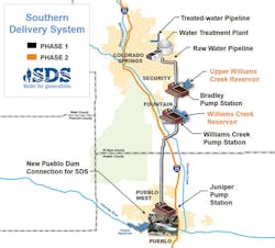
SDS would bring water north from the Pueblo Reservoir through a 50-mile pipeline. Three pump stations would be built to hoist the water up 1,500 feet in elevation. A new water treatment plant would be constructed on the east side of Colorado Springs.
A big hurdle for SDS was a 1041 land use permit from Pueblo County. Enacted in 1974, the Colorado House Bill 1041 lays out regulations for a variety of development uses. The permits are awarded by local governments for their own area.
Fountain Creek flows through Colorado Springs into Pueblo County, running into the Arkansas River. The creek has been a source of tension between Colorado Springs and Pueblo. After the Waldo Canyon wildfire, stormwater runoff from the burned hillsides flooded the west side of Colorado Springs and drastically increased flows in Fountain Creek. This led to negative impacts on Pueblo County. After long negotiations, an agreement allowed for the construction of the SDS system paired with $460 million in funding from Colorado Springs Utilities and the City of Colorado Springs to mitigate stormwater impacts on Fountain Creek. The final approval from Pueblo County came just three days before the project began supplying water.
John Fredell, SDS program director, credits a contracting mill with smoothing the permit process. A group of people worked full time on permits so that construction could proceed as quickly as possible. The permitting team handled permits for 300 parcels efficiently by having a well-structured process with forms ready to go without having to recreate them each time. “Be really flexible,” says Fredell. The construction started where they had permits.
FUNDING, RATES
Funding for SDS was obtained partially through bonds and partially by rate increases on Colorado Springs Utilities customers. The original cost estimate was $985 million. Rates were expected to increase by 12% from 2011 through 2017.
Due to value engineering, competitive bidding, and low-interest rates, the rate increases dropped to 10% in 2013 and disappeared by 2016, decreasing the expected rate increases by half.
Another source of funding was development tap fees. Those increased by 137%, adding about $9,200 to the cost of a new home. New residents are carrying their part of the funding.
VALUE ENGINEERING
One of the best decisions for the project was an idea called value engineering. According to Fredell, value engineering is a systematic, organized approach to obtaining value for every dollar spent. It means prioritizing function over form.
Two factors led to successful value engineering on this project. First, integrated teams were formed with Colorado Springs Utilities personnel and MWH Global to provide program management. MWH Global brought in expertise not easily available through Colorado Springs Utilities, reducing the need to hire for this project. At the start of the project, people from the utility took on SDS duties as an additional part of their jobs. Eventually, a full-time team was created, with utility personnel and employees of MWH.
Another important aspect was the open flow of ideas. A workshop with people from engineering, construction, health and safety, operations, and maintenance generated hundreds of ideas. The process of advancing creative ideas continued throughout the project and these ideas cut costs substantially.
Construction was divided into 20 work packages. This allowed companies to bid on a smaller section of the project, leading to more competitive bids. Smaller companies could afford to bid on a piece of the project instead of only large companies tackling the entire thing. SDS project leaders had committed to using 30% of local companies for the work. They succeeded wildly with about 70% going to Colorado businesses.
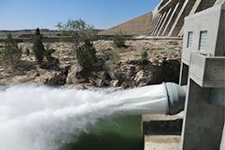
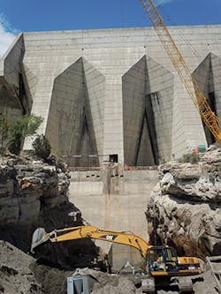
CONNECTION TO DAM
Here are the different components of SDS, traveling from the reservoir up to the water treatment plant. Construction of a connection to the Pueblo Dam was completed in summer of 2012. The connection required diversion of the water from that section of the dam to provide a work space. A round, liner pipe was inserted into the existing square tunnel that sends water from behind the dam to the river. A meter vault was built and a cone valve installed. A 90-inch pipe leaves the dam with the water for the SDS. A short segment of pipeline connects to the Pueblo West water system.
PIPELINE, TUNNEL
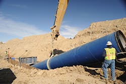
Pipeline construction started in 2010. Garney Construction was one of the main contractors for pipeline installation. Northwest Pipe Co., headquartered in Vancouver, WA, has a fabrication plant in Denver, CO. The steel pipe was mostly 66-inch with a polyurethane coating. About 7,000 lengths of 50-foot pipe were used.
One challenge for pipeline construction was that the 1041 land use permit required no more than 400 feet of trench open at a time in Pueblo County. So the contractors trenched 400 feet, laid the pipe, joined sections with a heat shrink sleeve, and closed the trench. Later welders crawled inside the pipe from access points and welded the joints. This is called “weld after backfill” and it cut costs while fulfilling the permit requirements. Another cost and time saving process was using single lap welds instead of double.
A tunnel for the pipeline had to be punched through under I-25, the railroad, and Fountain Creek. While safety was the top priority for the entire project, it was especially critical for this particular section. Two 105-inch tunnel boring machines (TBM) were used to drill the hole needed for the pipe, starting at each end and meeting in the middle. The tunnel is 85-feet-deep, 50 feet below the bedrock for the creek, and one mile long. The chance of groundwater breaking through was an issue, but was manageable. This tunnel construction required eight months for completion. Twelve tunnels were built for SDS, but this one, with its many variables, was the most challenging.
COMMUNICATIONS
The pipeline passed through 125 residential yards in Pueblo West. Six houses had to be removed and their residents relocated. Two full-time construction facilitators spent their time communicating constantly with homeowners and neighbors. Door-to-door visits and continual access to the facilitators by a 24-hour phone hotline cut down the amount of friction during the project.
The community benefitted from the houses that were removed. SDS donated any usable items from the houses to the local Habitat for Humanity. Then the houses were used as training areas for local fire and police.
Another successful means of communication was the SDS website. Monthly project updates, information, and news items provided communication for news organizations and the entire region. Each monthly update listed steps accomplished, as well as showed actual costs against projections.
PUMP STATIONS
Three pump stations were built along the 50-mile pipeline. Juniper Pump Station is near the Pueblo Reservoir, Bradley Pump Station comes next, and then Williams Creek Pump Station. Each pump station has 2,000 to 2,750 horsepower pumps. The pump stations raise the water by more than 1,500 feet in elevation.
The type of pump changed as the design advanced. The final decision was for vertical turbines, giving a 30-year lifecycle. The upfront cost was higher, but for the long term the pumps were more cost effective. The pumps were manufactured by Ebara Corporation in Japan. Motors and drives were shipped to Japan so that final testing with the pumps could be performed. The tests showed that the pump systems exceeded the estimated efficiency.
A problem developed with delivery of the pumps. Right when they were ready to ship, the west coast was having a work slowdown. To avoid paying a large claim, SDS personnel rented a big plane to fly two of the pumps to the US. This meant that work continued until the other pumps could be delivered in the planned manner.
To increase efficiency, the pumps are scheduled to use electricity at off peak hours, saving a significant amount of money.
The prime contractors for the pump stations and the water treatment plant were McCarthy Building Companies and Carollo Engineers.
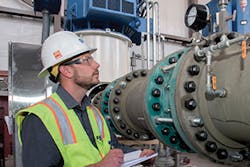
WATER TREATMENT PLANT
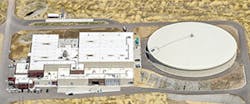
The Water Treatment Plant (WTP), built on the east side of Colorado Springs, is one of the most advanced in the state as well as in the country. The $125 million price tag makes it the most expensive part of the SDS project.
The original plan for the WTP was for a campus arrangement—different buildings for the various parts of the treatment process. As part of the value engineering process, WTP operators objected to that design. They wanted a single building to avoid having to go in and out during winter weather when checks needed to be made. The original design company didn’t like that idea, so that company was dropped. Another firm designed the WTP using the input from operators, putting all the components under one roof.
Another design change put the chemical delivery station on the south side of the building. Operators knew from experience in another plant in Colorado Springs that a north-facing dock can have ice buildup that lasts for days.
The first thing that a visitor sees at the site is the 10-million-gallon raw water tank. The tank was placed at the highest point of the property to take advantage of gravity as it feeds into the treatment plant. The pump stations send water to this tank during the off peak electricity hours, then it can be fed into the WTP at any time.
The 82,000 square-foot plant has two floors, giving easy access to piping and chemical tanks. The process starts with ponds where impurities are coagulated by the addition of ferric sulfate. Sulfuric acid is added to lower the pH to the six to six and a half range and enhance coagulation. Three basins range from faster to slower mixing. The coagulation process lowers the turbidity level and the amount of total organics.
The next step is sedimentation pools. Rods of stainless steel stretch across water basins. Holes in the rods distribute the water through the pool. Sedimentation plates set at an angle of 50 to 55 degrees force the sediment to settle, so that clear water can be piped off of the top. The turbidity measurement at this point is usually from 0.2 to 0.3, so it more than meets the EPA standards. Sodium hydroxide brings the pH level back to neutral.
Next, ozone is added to further breakdown microorganisms and algae. This process also improves taste and odor. The ozone is generated from liquid oxygen with dielectric rods. Ozone will not last long in the water, but long enough to do its job. Then the ozone is quenched by the addition of sodium bisulfite, so that it will not interfere with beneficial organisms in the next treatment.
The last process is filtration through biofilters. The filters are dual media with 1 foot of sand and 6 feet of granular activated charcoal. Beneficial microorganisms also grow on the media and help remove any remaining contaminations. Chad Sell, water treatment plant supervisor says that if these microorganisms are not treated right, they produce a sticky film that can really mess up the filtration media.
The usual method for inspecting filtration media requires removal of numerous bolts to remove a hatch. For this plant, two submarine hatches were installed, so that a wheel can be turned to open the hatch and reveal the layers of media.
After all these steps, the treated water is pumped into a treated water tank built underground. Minimal chlorine is added to finish the disinfection process. A finished water pump station above the tank sends the water into the supply system for the city.
The WTP is completely automated. Operators can see the results on screens at the WTP or on their smartphones or iPads, so 24-hour shifts are not necessary. Only six people work the entire system—one supervisor, three operators, one mechanic, and one instruments and controls person. The pump stations are unmanned, but monitored by personnel at the WTP.
Digital manuals were compiled by process area. Files in pdf format walk a worker through what needs to be done or known about each section. Training and maintenance work orders are completed in totally paperless procedures. Each piece of equipment carries a QRC ID so that a worker can scan the code and learn information about that part, when it was installed, its maintenance record, and present status.
Another safety measure is to completely separate raw and treated water pipes and valves on opposite sides of the building. The chemical storage tanks, pipes, and valves are also separated with acids on one side and bases on the opposite side to prevent any chance of a mixing accident. The chemicals are all in liquid form, which is easier and safer than using solids that have to be mixed correctly. The section where the sulfuric acid tank sits is like a building inside a building to protect the rest of the facility. It has a blast door that would blow to the outside and away from the other chemicals if by some outside chance water mixed with the acid and caused an explosive reaction.
The WTP uses a different process than other water treatment plants. Sell says, “It was a big learning curve.” But he went on to say that operations have gone smoothly.
The plant is built to produce 50 million gallons a day (mgd). Currently, it is dialed back to only 5 mgd. Fredell says that it’s very hard to get a plant to run efficiently at less than 10 mgd, but he credits the expertise of the plant operators in keeping it at 5 mgd.
The plant is the Edward W. Bailey Water Treatment Plant. It was named for a man who served a 34-year career working to bring clean water to Colorado Springs.
On April 28, 2016, the SDS began supplying water to Colorado Springs. The entire project was finished on time and $160 million under the beginning estimate.
EXPANSION POSSIBILITIES
One innovation of the SDS is that it is expandable. The part that’s now operating is Phase 1. When population growth makes it necessary, Phase 2 will start. Two additional reservoirs will be built next to pump stations. Each pump station has space for additional pumps to handle the load. The WTP is also built with space for additional treatment facilities. This means that Phase 2 can be accomplished without a new pipeline or pump station and WTP buildings. Total water treatment after Phase 2 would be more than 100 mgd.
LESSONS LEARNED
Fredell says one of the best parts of the project was the unwavering support from city officials, business leaders, the contractors on the project, the public, and from the team. He says one change he might make would be to start the full-time team a little earlier in the process. “Be prepared to spend money on project management,” he adds. “It’s worth it in the long run.”
Early in the project, people responsible for the SDS traveled to Salt Lake City to tour a recently-built water system. They learned from that project and now they are serving as an example to others. Water utilities professionals from around the country are interested in the success of the Southern Delivery System, and SDS people have been sharing their gained knowledge.