Pump System Longevity and Extreme Operating Regimes
A pump is a mechanism that utilizes mechanical force to overcome distance, elevation, and friction to move water or another liquid through a conduit to a point where it can be discharged, stored, or utilized. Like all mechanical devices, pumps can wear out or break over time. A pump’s operational lifetime and longevity of service is in direct proportion to the resistance it has to overcome while it is working. The greater the resistance, the greater the wear and tear on the pump. This resistance is measured in units of feet (or meters) of an equivalent column of water.
This is not just a physical measurement of height differential between the pump and its discharge point. It also includes resistance from friction by the sidewalls of the conduit as well as the constriction of the flow by the narrowness of the conduit and its resultant flow velocity. Both of these factors are also converted mathematically in feet of water column and added to the elevation difference to obtain the total head of the pipe or hoses that the pump is pushing water through. Pipe fixtures that result in turbulence or redirection of the flow also have equivalent head losses associated with them as determined by empirical testing. This article explores the relationship between pressure head and pump longevity, and the affect that pressure head has on pump equipment.
THE RESISTANCE
Pumps apply mechanical force in the form of total operating head to overcome resistance in pipe networks. This total operating head has three components, which are added together to determine the total head: static or elevation head, friction head, and velocity head. How is this resistance measured and what does this resistance consist of?
Resistance is measured in feet (or meters) of head using the unit density of water as a baseline. At standard temperature and pressure, water weighs approximately 62.4 pounds per cubic foot (pcf). A foot-high column of water would therefore exert a pressure of 62.4 pounds per square foot (psf). This is equivalent to 0.433 pounds per square inch (psi). If the base of the water column was 1 square foot in area, the force it delivers at its bottom would be 62.4 pounds. However, since the operation of a pump depends on pressure, the actual force delivered is not directly considered in evaluating pump performance, only pressure.
The same measure based on water density is used to evaluate system resistance and operating head depending on what liquid is being pumped. The relationship between these other liquids and standard water is defined by their specific gravity (SG). Specific gravity is defined as “the ratio of the density of a substance to the density of a standard, usually water for a liquid or solid, and air for a gas.” So, crude oil at a temperature of 130°F with a SG of 0.84 has a density of 52.5 pcf. A foot of head consisting of this crude oil would exert a pressure of 52.4 psf. Similarly, a heavier, more viscous material such as nitric acid with a SG of 1.50 would have a density of 93.6 pcf with a foot of head equal to 93.6 psf.
First off, there are direct elevation differences, referred to as static head. This is typically the primary component of the total operating head that a pump must overcome. Static head is calculated by measuring the vertical distance between the elevation of the pump inlet point and the elevation of the water discharge point at the end of the pipe system, regardless of the actual length of the pipe. Therefore, a pump with an inlet elevation of 100 feet and an ultimate discharge point 60 stories up in a skyscraper at an elevation of 600 feet has a static pressure head of 500 feet to overcome. This is true even if the pipeline involved snakes back and forth between floors, or even extends higher than the ultimate discharge point before bending around and coming back down to its discharge elevation. With any pipe configuration of any resultant length, its static head will always be 500 feet. In most cases, except in situations of very small diameter pipes or excessively long pipelines, the bulk of the operational head will consist of static elevation head.
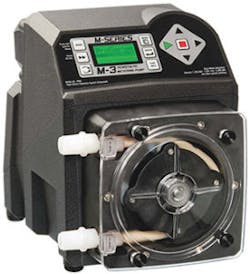
The M-3 peristaltic metering pump from Blue-White Industries
The length of the pipe comes into play when determining another component of total operating head: the friction head. This represents the loss of energy occurring as the liquid flow overcomes the resisting friction of the pipe’s interior walls. Determining friction head loss is a three-step process. The first step in calculating friction head is to determine the liquid’s velocity of flow. This is usually a simple matter of dividing the liquid’s flow rate—measured in cubic feet per second (cfs) or gallons per minute (gpm)—by the interior cross sectional area as defined by its diameter. The resultant velocity, measured in feet per second (fps) or meters per second, is used to determine the liquid’s “Reynolds number.”
The Reynolds number (a dimensionless number) is equal to the flow velocity times the pipe diameter and divided by the inherent viscosity of the liquid at its flow temperature (water at standard temperature has a viscosity of 0.0000141 square feet per second). Once the Reynolds number is determined, it is referenced to a standard performance curve for smooth-walled pipe operating under laminar (non-turbulent) flow regimes as shown on a Moody pipe flow chart. Evaluations can be made for turbulent flow on the same chart but a laminar flow is usually used as a simplifying assumption unless flow regimes are known to be turbulent. Cross-referencing on the Moody chart gives the “friction factor” (also dimensionless) for the evaluated flow. The resultant friction head loss is calculated by multiplying this friction factor (from the Moody chart) by the length of the pipeline (feet) and by the square of the flow velocity feet2/sec2), and then by dividing this value by a denominator calculated by multiplying the pipe dimeter (feet) by twice the acceleration due to gravity (32.1740 feet/sec2).
Utilizing the previously determined flow velocity, the velocity head loss can be determined. Since velocity is proportional to cross-section area for equivalent flow rates, this reflects the head losses from constricting the liquid’s flows. Velocity head is calculated by dividing the square of the velocity by twice the acceleration due to gravity (g = 32.2 feet/sec2). Velocity head is typically insignificant for all but very small diameter pipes.
In addition to the straight-up calculations for operational head based on elevation, friction, and velocity, pipe systems usually come with a wide variety of appurtenances and fixtures. Each of these pipe structures and instruments has its own unique head loss, measured in equivalent feet of head, and referred to individually as minor head loss. Their structures impede smooth liquid flows, and thereby cause turbulence as the flow impacts the fixtures. These fixtures and appurtenances include wyes, elbows, bend, flanges, meters, nozzles, etc. These have been empirically evaluated in testing laboratories that have established industry head loss values for each type.
THE FORCE
These characteristics, static head, friction head, velocity head, and minor head represent an equivalent load for the pump to overcome. The higher the overall operational head, the more work that a pump must do. The more work a pump must do, the more wear and tear it is subject to. The more wear and tear, the shorter the operational lifetime of the pump before it must be replaced. Pumps are designed for heavy duty operations and it’s these design changes that allow it to function in a harsh environment with heavy workloads. Therefore, the pump design and resultant operational characteristics are critical to the pump’s applicability. A mismatch between pump and operating system can result in a poorly performing pump operation or even a premature end to a pump’s operational lifetime.
Pumps in general are defined as devices that utilize mechanical force to raise, transfer, deliver, or compresses fluids (liquids or gases) by utilizing suction and pressure. Operations in harsh environments or extreme pumping loads require advances in energy efficiency, applied force, and the ability to deal with suspended particles and solids. This last point is important because a pump’s workload also includes the type of liquid is it pumping. Oil pumps will have different operational characteristics than pumps used for water distribution. Liquids containing fines, waste materials, or large solids like and gravel will require ruggedly built grinder pumps.
A pump can be sized to match the required operating head as well as flow rate and cycling time. However, even the best analysis is based on assumed values and laboratory test data which may not match actual field performance due to local conditions, modification to the system operation, or how the system was actually installed. So, prior to formal system start up, testing, dry runs, sampling, and measure are required to insure proper operation.
There are two basic types of pumps to choose from: centrifugal pumps and positive displacement pumps. There are also two basic locations for pump operation: submersible (placed in the liquid when pumping) and non-submersible (located above or outside the liquid reservoir). Pumps are designed for specific tasks and for managing different types of fluids (liquids and gasses). The liquids handled by pumps can vary greatly in material characteristics such as temperature, density, viscosity, suspended solids content, biological and bacterial content, slurries, sewage and pollution, sludges, oils and petrochemicals, leachate and digester distillate, etc.
Those liquids carrying significant quantities of particulate, contaminantes, and even large objects require the use of sump pumps, grinder pumps, sewage pumps, and effluent pumps. In general, these are ruggedly built pumps especially designed to manage these contaminantes, passing them on without physically damaging the pump itself. Some are designed to initially pulverize and even liquefy the objects floating in the liquid before it gets pumped into the piping system. They vary in size from sump pumps (for particles as large as fine gravel), to effluent pumps (for particles up to the size of medium gravel), to sewage pumps (which can handle cobble-sized objects as large as 2 inches in diameter). Each has different operating characteristics depending on the anticipated particle sizes. There is usually a trade-off between flow rate and pump head, with those pumps managing smaller particles utilizing higher flow rate, and with those managing larger particle relying on higher operating head. Grinder pumps are the kind that mechanically grind down the particles to a smaller size before pumping the liquid.
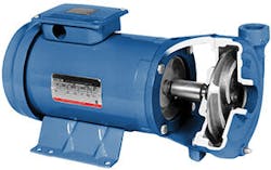
A Veriflow Model 1312 horizontal motor-mounted end suction pump
Of the two modes for imparting mechanical energy to pump liquids, positive displacement pumps literally push the liquid forward by means of a reciprocating piston driven by a rotating cam assembly, expanding and contracting bellows, or pulsating membrane or diaphragm. A unique method of positive displacement is the use of peristaltic tubing. This utilizes reciprocating rollers that alternate squeezing and releasing a flexible tube, forcing a slug of water forward with each contraction. This is especially important for liquids that must avoid cross-contamination since no mechanical part of the pump actually comes into contact with the liquid. This is the only type of pump that is found in nature (the human digestive tract works exactly in this fashion). It also has the advantage of functional simplicity and the ease of maintenance and repair.
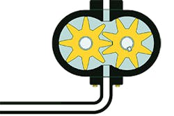
Centrifugal pumps do not push liquid so much as they fling it via a rapidly rotating impellor blade. The basic design includes a metal housing that encloses the spinning impellors with the liquid entering via an inlet port at the center of the rotating impellor axle. The spin carries the liquid from the center of the pump to the exterior wall of the housing at high flow rate but low operating heads. Variations include: flexible impellors that utilize elastic blades instead of fixed blades and whose shape can alter with operating speed, rotary fixed vanes, rotary lobes that use highly curve blades to manage viscous flows, gear pumps that use rapidly spinning enmeshed gears to squeeze the liquid forward.
To find the actual operating point for a pump discharging to a pipe distribution system, a comparison is made between the pump’s performance curve and the system’s resistance curve. Both are parabolic curves that compare flow rate to pressure head. The system curve shows high head with high flow, and low head with low flow. Conversely, pump performance curves show high head with low flow rate and low head rate with high flow rate. Where the two curves intersect is the overall pump system operating point where pump and system characteristics match up.
PUSHING THE ENVELOPE: THE EFFECTS OF EXTREME OPERATING REGIMES
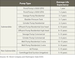
How long should a pump last? Its operational lifetime is a function of many factors, but certain types of pumps are designed to last for different durations. The table above provides a list of different pump types and their average life expectancy.
The primary cause of pump failure is material fatigue. Anything with moving parts will wear out over time due to friction- and heat-induced deformation. Friction and heat are proportional to workload. The greater the workload, the greater the material fatigue over time. The parts of the pump most susceptible to material fatigue include any that are subject to fluctuating or cyclic loading during operation. These include vanes which are subject to both suction and high pressure with each rotation, pistons subject to variable pressure as they move with each turn of the cam shaft, expansion and contraction of vibrating membranes, etc. The stresses imposed onto the materials by these cyclical loadings result in strains that propagate in opposite directions with each cycle. These microscopic cracks will get larger over time as they serve as pressure concentration points for subsequent loadings.
The key factor determining the extent of fatigue is the amount of the load versus the material’s maximum resistance. The closer each load is to this limit, the fewer cycles necessary to cause fatigue. This, simply put, is why higher workloads wear out pumps at a faster rate. The result is a significantly shortened operational lifetime. Maximizing pump lifetime depends on starting with an appropriate design configuration and operating the pump in good working conditions that avoid extreme workloads. Each pump model has a life rating assigned to it under normal operating conditions. A life rating is measured in terms of projected operating hours at a specific pressure range (measured in psi) and range of operating speeds (measured in rpm). This estimate is typically based on the pump’s shaft bearing life expectancy. It is up to the pump’s operator and the system’s designer to ensure that a pump does not have to exceed these operational limits.
Speed and pressure do not have equal effects on pump longevity. Pump operational lifetime is in direct inverse proportion to shaft rotating speed. Pump life can be doubled by reducing operating speed by half, or conversely it can be halved by doubling the rpms during operation. Pressure, on the other hand, has a much greater impact on pump longevity. Hydraulic pressure induces a side load on the shaft bearing. The side load is directly proportional to the hydraulic pressure. Pump life is inversely proportional to the cube of this resultant side load. So, doubling the hydraulic pressure of the pumping system would decrease to one eighth of its normal operational life. Or, halving the hydraulic pressure would increase the pump’s life by a factor of eight. This does not imply that pumps should be oversized and then run at lower-than-normal pressures and speeds to maximize longevity. This would be a false economy requiring more such oversized and under-run pumps to do the same amount of work.
In addition to pressure and speed, pump cycle time also affects pump longevity. The act of stopping and starting a pump induces several initial stresses into its material components. Constantly having to stop and start a pump results in significantly more wear and tear than continuous operation. Increased frequency of the start and stop cycle, can result in burning out the pump motor. While speed is an inherent characteristic of the pump, and pressure is a function of the pumping system configuration, cycle time is a consequence of the amount of liquid that is being moved and stored. Pumps can be configured to turn on once the water level in a reservoir reaches a designated elevation. This turn-on elevation is a function of the liquid inflow rate and the storage capacity of the reservoir, sump, or tank. There is also a turn-off elevation near the bottom of the reservoir whose depth is set to prevent pump cavitation that would result from having too little liquid to pump.
The duration of the “off” part of the pump cycle—the time needed to refill the reservoir—as determined by storage capacity (between the turn-off and the turn-on elevations) divided by the inflow rate. The pump is not operating while the tank refills. The duration of the “on portion” of the pump cycle—the time needed to empty the reservoir—is determined by the same storage volume, divided by the difference between the pump discharge rate and the liquid inflow rate (inflow is assumed to continue while the pump is operating).
OTHER FACTORS AFFECTING PUMP LONGEVITY
Excessive pressure and speed can cause pump failures by causing bearing shafts to prematurely reach the end of their useful life through material stress, wear, and tear. However, there are other extreme (and simply negligent) operating conditions that can reduce a pump’s operational lifetime. As mentioned above, cavitation can reduce pump longevity. Cavitation, the formation of bubbles in the liquid inflow is caused by insufficient head at the suction inlet point (due mostly to insufficient depth). It causes mechanical damage due to the shock of the bubbles’ impacts, excessive heat, etc. This can be avoided by maintaining the proper suction head at the inlet.
Misalignment of the pump rotating shaft can cause side bearing pressures like that of excessive hydraulic pressure. It also creates points of concentrated friction as the shaft rests against the casing sidewalls instead of rotating freely. It can also displace and ruin the shaft’s ball bearings. Proper care and maintenance should prevent this from occurring.
The lack of a pump relief valve or a relief valve set at the wrong release pressure will result in excessive pressure buildup within the pump. Operating at maximum pressure, even if not actually pumping liquid, is effectively counted as operating time reducing the pump’s actual life.
Oil cleanliness and oil filtration are necessary to prevent internal friction grinding and the buildup of gunk on the pump’s moving parts. Usually a 150-uM pump suction strainer is required along with a return line filter of 10-uM rating or better. Using even finer strainers will result in longer operational lifetimes. However, the installation of very fine strainers may be prohibitively expensive compared to the cost of replacing the pump over time.
In addition to oil cleanliness, oil temperature needs to be maintained. Heated oil cannot be used to dissipate operating heat and thus indirectly adds to material heat stress. Oil temperature can be controlled by means of a heat exchanger or radiator attached to the oil circulation line.
Vertiflo Pump Company manufactures close-coupled horizontal end-suction pumps designed for the transfer of both water and chemical solutions. The Vertiflo Pump Company offers its Model 1312 Industrial, close-coupled, horizontal, end-suction pump for service in general pumping, chemicals, wash systems, deionized water, process and OEM applications. This pump is designed for pumping liquid chemicals from tank to tank, and into transport delivery trucks. The Model 1312 is designed for long life in extreme operating regimes with heads to 160 feet total operating head and flows up to 240 gpm. 1750 and 3500 rpm sizes are available. Its back-pull-out design construction allows rotating element to be easily removed since the casing remains in piping. Casing may be rotated in 90-degree increments to accommodate various piping and discharge orientation requirements. The close-coupled design saves installation space. Suction and discharge connections are threaded NPT. Construction material options include cast iron, 316 stainless steel fitted, or all 316-stainless steel. Pump volute, impeller, and mounting bracket are heavy cast metal. Vertiflo’s Model 1312 horizontal motor-mounted, end-suction pumps are designed for use with NEMA standard C-face electric motors. Its standard size mechanical seal is a self-aligning design. The pump’s semi-open impeller with balance hub is secured to the bearing shaft by taper and threads.
Peristaltic metering pumps are designed to dispense accurate amounts of chemical to a system. Positive displacement is created by rollers which squeeze the tubing in the pump head through which the chemical flows. The maximum pressure that a peristaltic pump can support varies from pump to pump. Blue-White Industries’ Proseries-M FlexPro Peristaltic Metering Pumps have a max pressure rating of 125 psi (8.6 bar). As pressure increases, the longevity of a pump may decrease.
High-pressure pump discharge over a long period of time can cause greater wear on a peristaltic metering pump. The main components affected by constant high pressure are the discharge tubing, the motor, and the roller assembly. The tubing’s service life may decrease with maximum discharge. For example, there may be a greater occurrence of pinhole failure. This is when the fluid finds the weakest point inside the tube and pushes out towards the exterior of the tube, creating a tiny pinhole. Once there is a hole in the tubing, most pumps will fail. Each Proseries-M FlexPro Pump is equipped with the exclusive patented Tube Failure Detection system, built right in. The TFD System can detect tube failure and will automatically shut off and energize a relay, permitting communications with external equipment, such as an alarm or a SCADA system. The chemical must be cleaned from the pump head before the pump will restart.
The motor also becomes more stressed when more pressure is placed on the pump. High pressure causes more heat which can cause oil to leak. FlexPro pumps are less inclined to be affected by this issue because they are equipped with brushless motors. Brushless motors are more efficient and do not get as hot as brushed motors. The motor shaft breaking due to wear or high pressures is another problem that can occur. The FlexPro motors have a sturdy design to compensate for this added pressure. Each FlexPro shaft is hardened through a heat treatment process to withstand these external forces.
Roller assemblies will possibly wear with the higher discharge pressure. The bearings in the pump’s roller assemblies need to overcome the increased pressure in the tubing. When more pressure is put on the bearings, they may fail. FlexPro has two CNC-machined squeeze rollers and two alignment rollers. The rollers are made in-house and undergo rigorous quality testing to ensure precise control over tolerances, resulting in the parts ability to withstand greater pressures for longer periods of time. All peristaltic metering pumps will show normal wear when left running for long periods of time at high pressure. There will always be general upkeep and maintenance. When deciding what pump to purchase for a particular application, it’s important to take into consideration quality, repair and maintenance cost, and proven success.