Without a source of clean, safe water, neither individuals nor communities can survive. So perhaps the greatest invention of any civilization is a way to ensure clean, safe water. Supplying clean, potable water is both complicated and straightforward. The actual process is a relatively simple series of steps (extraction from groundwater or surfazce water sources, storage, treatment, pumping, and transmission via pipeline). The complexity occurs within each of these steps.
At each step along the chain of water delivery, care must be taken to prevent any contamination of the water that the water supply system has spent so much time and money cleaning and purifying to make it fit for human consumption. Keeping the water supply system components isolated from potential sources of contamination such as ponded water, surface water runoff drainage systems, perched groundwater, storm sewers, sanitary sewers, roof runoff downspouts, and combined overflow sewers is the first step. It is usually taken care of during the design of the system prior to its construction and operation. Each of these is a direct threat to the water supply and an indirect threat to human health.
One of the most common mechanisms of contamination is backflow. Similar to a siphon, backflows allow contaminants to enter a water supply pipeline. Therefore, pipe fixtures need to be fitted with backflow prevention devices. What are some of the best strategies for preventing backflow? What technologies are most useful?
For large communities, extensive and even multiple water sources are often required. A well field consisting of an appropriate number of water wells and associated pumps extracting water from a groundwater aquifer is one option. A second option is a surface water source. These include a natural freshwater pond or lake, a man-made reservoir created by a dam, or a free-flowing river. In all cases, the water source has to be able to supply water at the needed rate and have a recharge rate with precipitation and snowmelt sufficient to replenish the water and restore its pre-use volume and surface elevation. Each of the two primary types of water supply—groundwater and surface water—has its advantages and disadvantages. Surface water has a potentially greater flow rate, while groundwater is less prone to water loss via evaporation.
Once extracted, the water must be delivered to the community via the second component of a water supply service, the conveyance system. These are a series of very large pipelines and associated structures of various designs and sizes referred to as aqueducts. Aqueducts are designed, constructed, and sized to convey the necessary amount of water from the source to the water treatment plant and beyond. Whether they are ancient Roman aqueducts and Persian qanats, pipelines feeding melt to the farmers of California’s Imperial Valley, or the huge underground pipes feeding water to New York City, aqueducts have always been the prerequisite of any civilization.
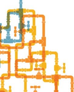
Conveyance systems begin as large individual pipes and branch out into a series of diverging and looping pipelines. The large pipes are the water mains, designed to carry large amounts of water at high flow rates over long distances. This is the type of pipe used to carry water from the source to the initial treatment facility. From the treatment plant, the conveyance system’s function switches from transport to distribution. Beginning with mains sized from 6 inches to 8, 10, 12, and 16 inches in diameter, the system branches out further to supply pipelines servicing individual homes and businesses. While transmission mains are often made of large diameter reinforced concrete pipes or even concrete-lined tunnels, distribution pipelines are made from a variety of materials such as polyvinyl chloride (PVC), high-density polyethylene (HDPE), cast iron, ductile iron, copper, steel, asbestos cement, and reinforced concrete.
Individual service pipes differ further. Made of lead or type K copper, these pipes have smaller sizes, varying from 0.5 inches to 6 inches in diameter depending on the required flow rate. As it arrives at its end-use point, the water flow passes through a water meter which records its flow rates for billing and record-keeping purposes.
Their structural design varies as much as their material characteristics. Pipe wall thickness along the materials’ modulus of elasticity determines a pipe’s resistance strength against applied loads and internal pressures. External applied loads are a result of overburden pressures (determined by both depth of burial and type of bedding used to reinforce the pipe). Each type of pipe material has a different thickness rating—schedule 40 or 80 for PVC, standard dimensional ration (SDR) for HDPE, iron pipe size (IPS) for iron pipe, etc. Choice of pipe material comes with tradeoffs. Traditional cast iron pipe is cheap but brittle and prone to breakage. Ductile iron pipe is more durable but also more expensive.
Internal applied pressures are limited by the need to protect supply plumbing used by homes and businesses. This requirement effectively limits the range of internal operating pressure to 50 to 100 psi. The minimum pressure required for discharge points such as faucets is 14 psi for open-air gap discharges or 20 psi for discharge points submerged under an existing tank or body of water.
The third component is the water treatment system mentioned above. This point defines the first stage of the water conveyance system. These are facilities that utilize mechanical and hydraulic processes to remove impurities from the water supply. These impurities include organic debris, silt and sediment, dissolved metals, bacteria and other pathogens, and so on. These methods include chlorination, aeration, coagulation and flocculation, adsorption, filtration with pros media (sand) or membranes, and UV disinfection. The end result is water fit for human consumption.
A fourth component is distributed throughout the conveyance system at optimum points like nodes on a network. These are the short-term storage facilities (towers, tanks, cisterns, secondary reservoirs, lined ponds, etc.) that provide surge capacity to control variations in water demand throughout the day. The surge capacity provided by water storage tanks is necessary since water usage rates never exactly match water supply rates. Tanks are required to safely store water during off-peak hours for later use during periods of peak demand.
LAWS, REGULATIONS, LOCAL CODES, AND BACKFLOW PREVENTION
The need to maintain safe water supplies and prevent contaminant backflow is outlined in the Code of Federal Regulation, including that buildings and facilities “provide that there is not backflow from, or cross-connection between, piping systems that discharge waste water or sewage and piping systems that carry water for food or food manufacturing.” (Source: “Food and Drugs,” Food and Drug Administration, Code of Federal Regulations, title 21, sec. 110.37, www.fda.gov).
The overall protection of our clean water supply is entrusted to the United States Environmental Protection Agency (USEPA). This authority is given to it by the Safe Drinking Water Act (SDWA) which authorizes the USEPA to set national health-based standards for public drinking water. The USEPA sets the technical standards and regulatory requirements for water supply systems, which are further enforced by state and local governments. At the local level, there are usually requirements for annual testing and certification of backflow prevention devices attached to local and individual water supply pipelines. As with most environmental regulations, the Federal government can grant enforcement primacy to local and state governments, provided that they adopt and enforce drinking water standards that are at least as stringent as the basic Federal regulations. Federal law allows state and local governments to go even further, letting them establish and adopt additional standards so long as they do not conflict with Federal regulations.
THE PHYSICS AND THE MECHANICS OF SIPHONAGE AND BACKFLOW
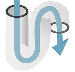
Siphons seem to defy gravity. Science has several explanations for this behavior. A siphon’s configuration consists of a reservoir of liquid exposed to ambient air pressure, a tube-shaped in a hump with a high point, which discharges into another container at a lower elevation that is also exposed to air pressure. The height differential results in the tube being shorter at the intake end before the high point in the hump and longer at the discharge end after the high point.
For the most part, siphons are driven by the force of air pressure. The liquid is initially sucked into the tube, completely filling it over its whole length. The liquid in the longer discharge end weighs more and drains out of the tube. As it does so, it creates a zone of low pressure at the top of the hump. When it does, the decreased pressure causes the air pressure acting on the surface of the water in the storage reservoir to push the liquid up into the tube towards the hump’s low-pressure zone. In doing so the water flows over the hump and continues down the longer end of the tube to the discharge point.
In addition to air pressure, the cohesion of the liquid adds to its movement through the siphon tube. Tests of siphons in a vacuum (the absence of any air pressure) still work. As gravity pulls the liquid down from the longer discharge end, liquid cohesion allows it to pull additional liquid from behind it, creating a chain of discharging liquid.
Backflow is the result of either back pressure or siphonage. Of the two, siphonage is more common, since back pressure requires that the system pressure increases so as to overcome the supply pressure, and there are relatively few mechanisms that can cause this to happen. Back pressure is analogous to blowing liquid into a straw. Something similar happens in back siphonage, only instead of an increase in system pressure, there is a decrease in supply pressure. This can occur when a supply is interrupted, drained down, etc. Siphonage is analogous to sucking liquid out of a straw.
The mechanics of backflow require a more detailed explanation. The physical movement of backflow occurs when liquids within the pipeline distribution network flow backward against the system’s designed flow direction. Physical failure (a breakage or crack in the pipeline) can result in loss of upstream pressure. These breaks can be caused by shifting foundations, vibration from vehicle traffic or equipment operations, valves and fixtures that break or wear out over time, or a simple mechanical failure of a key pump providing needed pressure head.
The reverse flow can create a suction that effectively pulls contaminant-containing water back into the pipeline itself. The resulting impact on water supply is called “indirect cross-contamination.” Back pressure, on the other hand, results in contaminants being forced into the pipeline by exterior pressure. This mechanism is referred to as “direct cross-contamination.” A true siphon can occur in water supply systems when an open faucet or other discharge point that is left open and submerged in a body of water, such as a sink or storage tank, gets subjected to a sudden loss of pressure in the supply line.
Once inside the water supply system, another mechanism occurs at the molecular level to ensure that the contaminants get widely spread. This is diffusion through water either spreading while it is not moving or being carried by flows when the system is delivering water. Even small quantities of pollutants can have a serious impact on both the real quality of the water supply and the public’s perception of its cleanliness. With strict federal and state regulatory standards, even a small amount of contamination can render a water supply undrinkable.
For a health-threatening backflow to occur, a cross-connection has to be collocated with a contaminated source of water. Cross-connections can be both internal (water supply and a building’s fire control system water, kitchen sinks, inside appliances such as dishwashers, clothes washers, water heaters, etc.) or external (ground water, sanitary sewer lines, combined overflow sewer pipelines, blocked drain lines or lines partially filled with sediment, septic tanks and cisterns, swimming pools, irrigation systems and lawn sprinklers, fish ponds, run-off from compost piles, drinking troughs for farm animals, a water well in addition to the water supply utility, a tank or bucket containing dangerous chemicals, recycling tanks used to collect and reuse gray water, etc.). Combined overflow sewers are especially dangerous after heavy rainstorms cause them to back up into adjacent basements.
Potential contaminants are both organic and inorganic in nature as well as either man-made or natural. Depending on the cross-connection’s location, contaminants may include soaps, bleaches, and other chemicals from laundry or dry-cleaning operations. Outside contaminants can include fertilizers, fungicides, insecticides, and pesticides from lawn applications. Natural sources can include simple silts and sediment, as well as soil bacteria. Industrial operations can produce fuel, oil, and grease from various mechanical systems. HVAC system can produce drips of anti-freeze and coolants. Old paint can peel off of walls and flake into areas where water has accumulated such as next to a house or inside an old water storage tank. Other water supply fixtures can contain toxic chemicals from tanks descaling or power wash operations. Lastly, fecal matter from sanitary systems and their associated pathogens are perhaps the most dangerous contaminants.
TYPES OF BACKFLOW PREVENTERS
Given the potential dangers of backflow, what devices are available to protect our water supply and what are their operational standards? In most cases, the law requires at minimum a double check (DC), reduced pressure principle (RP) device, or at least an air gap when backflow prevention is mandated. The simplest and most common air gap can be found in any kitchen sink. According to most plumbing codes, the end of the faucet must be at least one-inch higher (or twice the diameter of the faucet opening) than the highest water level in the sink. This one-inch difference establishes the air gap necessary to prevent the siphoning of dirty gray water in the sink back into the water supply pipeline from occurring.
This sink air gap is just a configuration of the plumbing. Mechanical means of preventing backflow are more complicated. There are several kinds of backflow preventers each suitable for a unique application:
- Barometric Loop. This the simplest of the backflow prevention configurations. It is a simple section of pipe rising 35 feet above the service pipeline which then loops down and reconnects with the pipeline. Since the maximum possible siphon height given ambient air pressure is almost 34 feet at sea level, a loop of one foot higher prevents a siphon from happening. Though it is simple and does not require valves or other mechanical devices, it cannot stop back pressure and is typically too high to be practical for most applications.
- Vacuum Breaker Assembly. This is the simplest configuration of the mechanical preventers. It consists of a movable disc and atmospheric vent. If a siphon occurs, the pressure in the valve will drop below atmospheric pressure. The vent will then open allowing the entry of air and breaking the siphon.
- Double Check Valve Assembly (DCVA). This is the most commonly used backflow preventer. Unlike the barometric loop, a check valve can protect against both backflow and back pressure. Arranged in a line, each check valve operates independently. Four test cocks are attached that allow an operator to test the tightness of each check valve and ensure that they are not forced open by debris lodged in their openings. A check valve is spring-loaded with a spring sized to allow normal flow to pass through above a certain operating pressure (typically 1 psi). Should backflow occur, both check valves close tight, preventing the intrusion of contaminated water. This is used where potential contamination is moderate (aesthetically unpleasant, foul taste or odor to drinking water).
- Double Check Valve Assembly with Intermediate Atmospheric Vent (DCVA-IAV). Designed for compact applications in limited space, this version of the DCVA includes a vent located between the two check valves. This is referred to as an air break chamber and allows for the release of excess pressure to the atmosphere. If siphonage or backflow occurs, the pipeline pressure drops to zero and the vent opens allowing air to enter the chamber, creating a break in the water flow.
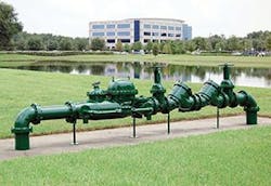
- Reduced Pressure Zone. This is the most complex backflow preventer, consisting of five independently operating valves, including two separate check valves, a differential relief valve in the center, and a pair of watertight valves at the ends. Each component serves as a back up to the others. The two check valves open and the relief valve remains closed under standard water pressure and flow. The relief valve will open if one or both check valves are clogged open, or if back siphonage occurs. Additionally, the downstream check valve will close and prevent the entry of downstream water. This is best used for situations where the potential contamination is severe (health threatening).
A MAJOR SUPPLIER OF BACKFLOW PREVENTERS
Cla-Val, a supplier of maritime piping and fixtures, provides backflow preventers that ensure potable water for crews and are also used for seawater isolation. The Cla-Val RP-2M Series backflow preventers are designed to isolate potable water supplies from seawater and range in size from ¾ inch to 1 inch, and 1½ inch. The larger RP-9M is available in 2½ inch.