Maintenance will never be exciting. But it’s necessary work required to ensure that a pumping system operates when you need it. If pump operation was a football team, maintenance would be the offensive linemen who do the grunt work in the trenches of the scrimmage line and make possible the exciting plays and athletic prowess that make the quarterback so famous. But no quarterback, no matter his athletic prowess, would be anything but a defender’s tackling dummy without a strong offensive line in front of him. So, let us for once shine the limelight on repair operations and examine their requirements. Let us take a close look at pump maintenance. What are the essentials? What practices are recommended by manufacturers?
PUMP OPERATIONS AND ENGINEERING
Two characteristics define a pumping operation and flow rate: the pump’s performance and the system’s resistance. A pump performance determines the flow rate the pump can produce for a given pressure head. Flow rates are typically measured in gallons per minute (gpm), while pressure heads are measured in equivalent feet of water column. Water at standard pressure and temperature weighs about 62.4 pounds per cubic foot (pcf). At 144 square inches per square foot, the pressure exerted by a 1-foot-high column of water is equal to 0.433 psi. The relationship between a pump’s operating head and its generated flow rate is called a pump performance or characteristics curve. This curve is drawn on a grid with the y-axis being head (in feet) and the x-axis representing the flow rate (in gallons per minute). The curve inflects downward from a maximum head at the y-axis (when the flow rate is zero) to maximum flow rate at the x-axis (when the head is zero).
In addition to the pump’s performance curve, there are three other curves that define a pump’s operating characteristics: the efficiency curve (measured in percent), the brake horsepower (BHP) curve (typically measured in watts), and the pump’s Positive Suction Head (NPSH). The first two are roughly parabolic and help to define the pump’s recommended operating range (as defined by its flow rate). The efficiency curve starts at 0% at the point of zero flow and zero head (the grid’s origin point) and continues to a peak that determines the pump’s Best Efficiency Point (BEP). From there it curves down again to 0%. BHP is represented by a shallower parabolic curve that starts at the minimum BHP associated with maximum head and zero flow of the performance curve, peaks near the BEP, and declines again to the minimum BHP required for maximum flow and zero head. BHP is defined as “the available power of an engine, assessed by measuring the force needed to brake it.” Peak BHP occurs within the pump’s recommended operating range. There are two definitions of NPSH. The first is available head (NPSHa) and the second is what is required (NPSHr) by the pump without being subject to potentially damaging cavitation and resultant reduction in pumping output.
The system resistance curve compares the system’s resistance head, measured in feet, to the allowable flow rate, measured in gallons per minute. Total resistance head is the sum of the elevation head difference between the pump’s outlet and the pipe system’s discharge point (the static head), the friction head lost as a result of water flowing along the surface of the pipe’s interior walls, and the head loss from the water’s flow velocity through the pipe (determined by dividing the pump’s flow rate by the pipe’s cross-sectional area). Since the static elevation head is a constant, the system resistance curve intercepts the y-axis (when the flow rate is zero) at a point equal to the static head. Static head is positive when the discharge point is higher than the pump outlet, zero when the two are at the same elevation, and even negative should the discharge point be physically negative (in this last case, the total system head would require large values for friction and velocity head from a complicated and long plumbing system to even require a pump in the first place). From the y-axis, the system resistance curve inflects upward to a maximum head value associated with the maximum flow rate that can be generated by the pump.
So how do these curves define the pump’s operating state in terms of flow and head? This occurs at the point where the system resistance curve intersects the pump performance curve. To maximize operational efficiency, it is best to choose a pump whose performance curve results in an operating point that coincides with the pump’s recommended operating range (flow rate) as defined by the efficiency curve.
TYPES OF PUMPS
While pump engineering is based on standard performance characteristics, pump mechanics are highly variable and utilize a wide variety of methods to move water through a pipeline. There are two major types of pumps: centrifugal and positive displacement.
Centrifugal pumps use a set of rapidly spinning impellor blades. As these impellor blades spin around an axis, centrifugal force causes the water to travel along the surface of the blades to the outer rim of the impellor assembly. Water enters the impellor unit through a port in the axis, and in effect, the spinning blades fling the water outward. The force imparted by the rotation forces the water out of the impellor casing via a discharge port built into the pump’s outer housing. In general, centrifugal pumps generate high flow rates with relatively low operating heads. The lower operating heads result in lower operating costs, making centrifugal pumps a cost-effective choice for high volume water removal. There can be many variations of the impellor design. One option is a pump that utilizes flexible impellors instead of stiff, fixed vanes or blades. The centrifugal force of the rotation also distorts these flexible blades, allowing them to trap a larger amount of water and expel it from the pump. Fixed, stiff impellors can use complicated curved lobe shapes or simple flat fan blades, with a tradeoff between cost and performance.
Some centrifugal pumps do not use blades or impellors at all, but instead rely on rapidly spinning enmeshed gears. Similar to a peristaltic pump (see below), the enmeshed gears trap, squeeze, and pinch water to a space between the gear teeth and use the rotary motion and centrifugal force of the spinning gears to expel water from the pump. Centrifugal pumps also come in submersible (designed to be placed below water level) and extraction (which operate from above the level of water being pumped) varieties. Submersible centrifugal pumps get their power from a vibrating drum, which can operate underwater without the need for direct electrical power. While operating underwater is not considered a harsh environment, certain applications and fluids definitely are. These include water with high turbidity (high amounts of total suspended solids), unfiltered groundwater, water with large suspended objects such as rags or green waste, raw municipal sewage, leachate from solid waste and hazardous waste landfills, industrial water pollution and spillage, and diesel and gasoline, as well as unrefined oil, viscous fluids and oil, heavy slurries, and sludges.
There is a direct correlation between the size of the objects suspended in the water or other liquid being pumped and the amount of energy required by the pump, as well as an inverse relationship between object/particle size and pump head. For suspended objects up to the size of fine gravel (diameter of 0.375 inches) sump pumps are used. For the range between fine gravel and medium gravel (0.5 inches), there are effluent pumps. For objects between medium gravel and cobbles (up to 2.0 inches in diameter), sewage pumps are utilized. Larger than this, specialized grinder pumps are required that will crush these objects down to a finer particle size prior to actual pumping, resulting in a thick slurry. Furthermore, the flow rates decrease with increased size. And as the object sizes increase, the amount of energy needed for pumping increases and the pumping head falls. The final result is the grinder pump, which requires very high horsepower and creates a low flow and low head pumping operation.
Positive displacement pumps “push” instead of “fling.” They utilize a reciprocating mechanical device, such as a piston inside of a cylinder, which pushes water out of a chamber and propels it out through the discharge pipelines. Other types of reciprocating mechanisms include bellow cavity, vibrating diaphragm, or drumhead squeezing a peristaltic with a pair of pinch rollers and syringes. This last type differs from pistons in that they operated at low flow rates but high-pressure heads. In fact, displacement pumps in general are capable of operating at high operating heads while generating low flow rates (the opposite of typical centrifugal pump performance).
No matter the mechanical design, performance characteristics, or operational applications, all pumps have one thing in common: the need for an exterior power source. This power source is either mechanical (from a reciprocating internal combustion engine) or electrical (from a battery or turbine power source). How much power any pump requires is relatively simple to calculate. Power requirements are a function of the pump’s mass flow rate (cubic feet per second or cfs), the density of the fluid (62.4 pounds per cubic foot or pcf, for water at standard temperature and pressure), the differential head (measured in feet), and the acceleration due to gravity (32.17 feet per second squared). Multiplying these values together and a conversion factor and the result is power requirements expressed in horsepower. This is referred to as the pump’s brake horsepower, the power actually used to perform the work. The pump’s rated horsepower is larger than this value depending on the pump’s efficacy rating. For example, a pumping operation requiring 120-brake hp to pump water would require the use of a 150-hp pump operating at 80% efficiency.
MAINTENANCE VS. REPAIR, AND AVOIDING DAMAGE IN THE FIELD
It is easy to get maintenance and repair confused. Even experienced operators can make that mistake. Maintenance is performed so that repairs can be avoided. Anything with moving parts requires maintenance, while repairs are completely avoidable. Maintenance is planned as part of a regular operating schedule; repair events are unwelcomed surprises. Maintenance is a cost of doing business, no different than the cost of labor or fuel needed to operate a pump or other piece of equipment. The costs associated with repair extend far beyond the direct costs of labor and parts involved in the actual repair work. Repair creates opportunity costs in terms of schedule delays, lost production, even safety violations and potential property damage or personal injury. In short, maintenance saves money and repairs cost money. Any attempt to skimp on maintenance is a classic example of a false economy. Shirking on maintenance makes major repairs almost inevitable.
“An ounce of prevention is worth a pound of cure” goes the old saying. So, the first step in proper maintenance is setting up the pumping operations to prevent damage in the first place. Damage typically results from either cavitation or clogging. Cavitation is defined as “the formation of bubbles or cavities in liquid, developed in areas of relatively low pressure around an impeller. The imploding or collapsing of these bubbles can trigger intense shockwaves inside the pump, causing significant damage to the impeller and/or the pump housing” (Source: Crane Engineering, “What is Pipe Cavitation?”, www.blog.craneengineering.net/what-is-pump-cavitation). These bubbles, as small as they are, can cause a series of micro-explosions and impacts with the pump itself. The shocks and vibration created by cavitation can over time damage the pump housing, impellor blades, seals, bearing packages, and pipeline connections. In the end, the pump loses both flow and pressure until it fails completely.
Cavitation can occur at either the suction or discharge end of the pump. Suction cavitation results when the pump is left to operate in a low-pressure regime (caused by poor pipe system design, not meeting the pump’s NPSHr standards, or partial or complete blockage of the intake and its filters) resulting in the pump not receiving enough water inflow. Air bubbles then form at the impellor inlet and travel along the vanes to the discharge—all the while impacting the blade surface. This can cause pitting and scarring of the impellor blade surface, and even the formation of holes that resemble Swiss cheese. The resultant rough surface further degrades pump performance and leads to increasing damage and further cavitation. Conversely, high pressure at the pump’s discharge point can cause discharge cavitation. Excessively high pressure at the receiving end makes it difficult for water to exit the discharge pipe which in turn makes it difficult for water to exit the pump itself. Bubbles then form along the interior surface of the pump housing walls, creating the same impact and shockwave damage caused by inlet cavitation.
In addition to avoiding those system characteristics and operational settings that make cavitation more likely, active measures can be taken to minimize the potential for cavitation. First and foremost, the filters and strainers at the pump’s intake should be checked and cleaned on a regular basis. Clogging of any kind can create the pressure imbalances that lead to cavitation. In many cases heavy filtration including mounds of filter stones and layers of geotextile are required in the field to prevent suspended solids from entering the pump. The pump’s operation should be monitored to ensure that it is working within the acceptable zone and preferably at the pump’s best efficiency point. Conversely, the piping system receiving discharge from the pump can be modified to eliminate the pressure differential that can lead to cavitation.
In addition to clogged intakes, clogging and biological buildup can affect the operation of a pump’s control switches. This is true of both pressure transducers located in the nose of a submersible pump or a floater switch. Dirt, plant growth, floating objects, mold, and bacterial scum can affect the linkages and connects that turn a pump on and off. Failure to turn a pump on can lead to overflow and flooding. But failure to turn a pump off when the water level has dropped below an acceptable head level can cause the pressure differentials that lead to cavitation. Lastly, there is the problem of ice formation, which can be considered to be a special type of floating debris. Ice clogging, either partial or complete plugging, can damage a pump during operation by preventing discharge and causing cavitation to reduced discharge flow rates.
MONITORING, INSPECTIONS, AND MAINTENANCE
In short, there are a half-dozen pump operating parameters that have to be monitored to ensure proper pump operations: intake pressure (feet), outlet pressure (feet), flow rate (cubic feet per second), pump speed (revolutions per minute), pump efficiency (percentage), and power requirements (watts). In addition to direct monitoring of the operating pump, vibration and noise levels should be checked along with any service fluids such as the fuel tank (and fuel consumption rates) and oil reservoir levels. Monitoring of these parameters is the next best thing to performing actual maintenance. It is less costly in terms of labor and time (no need to dismantle, maintain, or clean the pump) and does not require the pump to be temporarily brought offline. Furthermore, the accumulated data from this operational monitoring can be used to better plan the frequency and type of maintenance required to keep the pump functioning.
Pump inspection schedules typically follow routine, quarterly, and annual cycles. Routine inspections (weekly to monthly) should examine oil level and condition, noise and vibration, bearing temperatures, leaks from the pump housing, leaks from pipe connections, cracks in pipes or hoses, discharge pressure, intake pressure, seal integrity, and operating temperature. Quarterly inspections include checking the mechanical seals, changing the oil, and shaft alignment. Annual inspections include checking the pump’s capacity, pressure, and power requirements.
Maintenance regimes require a certain standard set of procedures. These include:
- Lock-out and tag-out of all power sources, including shutting off of all power switches, removing electrical fuses, shutting down the control panel, closing off all valves, and disconnecting or otherwise shutting off any fuel or oil service lines to the pump. In other words, disconnect anything carrying any kind of electrical, hydraulic, or mechanical power from the pump. Rotating parts (couplings, belt pulleys, external fans, spinning axles, etc.) especially have to be shielded from contact by people or clothing.
- Examine the pump’s foundation and ensure that the anchor bolts are tight and firmly in place.
- Make sure that pump vibration has not caused it to misalign with its power source, intake piping, or discharge piping.
- Key lubrication points (such as the ball bearing package) need to be inspected to ensure that they have sufficient lubricant and that their moving parts have not been subject to wear and tear along their contact points. Similarly, shaft seals need to be examined in order to ensure that there has been no leakage or loss of lubricants.
- Often the pump requires a complete internal examination requiring disassembly and reassembly. This time-consuming process usually requires that the pump be temporarily replaced with a backup pump during the inspection process. Furthermore, a ready supply of spare parts should always be kept on hand to minimize the wait time to get the pump back online. Not having to order parts greatly reduces any delays caused by delivery times.
MAJOR SUPPLIERS
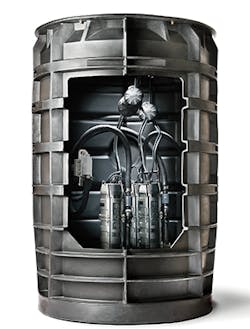
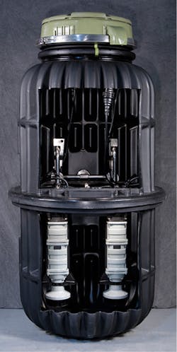
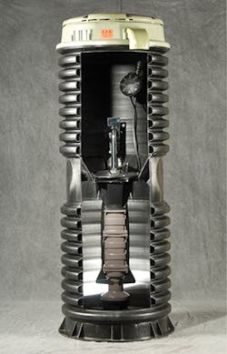
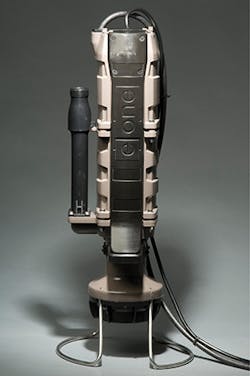
Environment One manufactures a series of different pump product lines. Their D-Series is available in a range of station heights to accommodate shallow to very deep burial requirements. Completely assembled stations are available with one or two grinder pumps. The W-Series provides flexible applications with a variety of basins, covers, discharges, inlets, and panels and completed stations with up to four grinder pumps. The Upgrade is a replacement grinder pump engineered to fit into virtually any grinder pump wet well. Universal design allows easy drop-in conversion and easy connection. The Upgrade is a complete replacement with all components of a centrifugal pump, including slide rails, pump/motor, float switches, piping, and motor control devices in one package. It comes with its own self-contained level control system, eliminating the need for float switches.
For more than 80 years, Gorman-Rupp Company has manufactured high-performance, high-quality pumps and pumping systems for the municipal, water, wastewater, sewage, industrial, construction, petroleum, fire, and OEM markets. They do so with a product line as varied as the markets they serve: self-priming centrifugal pumps, standard centrifugal pumps, submersible pumps, trash pumps, priming assisted pumps, rotary gear pumps, and lift stations. Complete lift station and booster station packages are also available and include pumps, motors, controls, piping, accessories, and enclosures. These ReliaSource lift stations include above- and below-ground pumping stations. Their Prime Aire and Prime Aire Plus venturi priming system offers automatic priming and repriming for sewage bypass operations and construction site dewatering.
Since 1981, the Vertiflow Pump Company has concentrated on manufacturing vertical process pumps, sump pumps, end suction pumps, and self-priming pumps in cast iron, stainless steel, and special alloys. Vertiflo Pump Company’s vertical, horizontal, and self-priming pumps offer up to 3,000 gpm, 250-foot heads, and 26-foot depth. The horizontal end suction pump line offers up to 3,000 gpm and 300-foot heads. Their seal-less vertical pumps are designed for service in water, chemicals, sewage, and slurries. The Series 2100 industrial trash- and solids-handling self-priming centrifugal pumps have an oversized, tapered bore, a self-flushing seal chamber, and an optional external flush, resulting in greatly extended seal life. The Vertiflo Stormwater Vertical Immersion Sump Pump Series 800 is designed for sump drainage, flood control, and process drainage while operating with heads to 230 feet, 3000 gpm, and 350°F.
Sulzer Pumps provides a wide range of products for engineered, configured, and standard pumping solutions as well as essential auxiliary equipment. Sulzer offers a complete range of low and high pressure, horizontal and vertical axial flow pumps (also known as elbow or propeller pumps, they are used in high flow and low head applications) especially designed to handle severe pumping conditions. Their CAHR pump range has been designed for high flow and low head pumping applications. Submersible drainage pumps J and XJ are used for pumping water and dirty water mixed with light abrasives. Pumps with built-in AquaTronic unit will always have correct direction of impeller rotation, ensuring peak performance and reduced wear. Their HPH and HPL are multistage ring section pumps, designed for operation at two or four pole motor speeds. They are suitable for pumping clear or slightly polluted water with abrasive particles.