Recent Trends in Pressure and Level Sensing
The technology behind pressure and hydrostatic level transmitters has progressed in recent years, enabling price-performance relationships never before possible. Only a few years ago, features such as dual analog + digital outputs, field re-rangeability and low total error band accuracy was available only in high-end models, making their application practical only in the most critical applications. Now, due to advances in sensor technology and signal conditioning electronics, these features are available in many mid- and even low-priced models.
The three major components of any pressure or hydrostatic level transmitter are the sensor, the signal conditioning electronics and the mechanical packaging. In terms of the number of units produced per year, the most common sensor used in the production of pressure and hydrostatic level transmitters is batch-fabricated piezoresistive silicon. Originally developed in the late 1960s at the Honeywell Research Center in Minneapolis, MN, this technology lends itself well to pressure and level sensing, as its inherent features include low cost, small size and negligible hysteresis. The basic sensor must be isolated from the input media if it is to operate reliably, especially in the case of liquids.
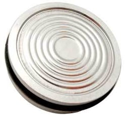
Today’s state-of-the-art media isolation package is compact, uses a flush-welded isolation diaphragm and is made from either 316L stainless steel, Hastelloy C-276 or 6Al-4V Titanium, depending upon the application. The flush-welded diaphragm design is a “best-of-both-worlds” solution, leading to lower cost and insuring that exposure to low concentrations of harsh chemicals or occasional exposure to salt or brackish waters will not cause premature failure due to crevice corrosion.
All sensing technologies have inherent static errors (at a constant “reference” temperature, usually room temperature) and thermally induced errors (as the temperature varies up or down from the reference temperature). Typical static error specifications range from ±1% down to better than ±0.1% of Full Scale. The 1% spec is appropriate for nominal applications where extreme accuracy is not required (e.g., lift station pump control) while the 0.1% spec is needed where surface areas are relatively large (e.g., reservoirs and aquifers).
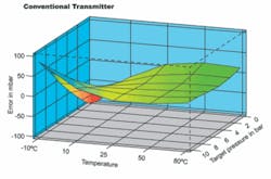
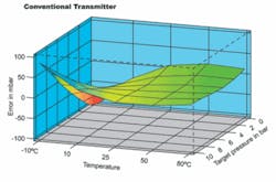
Temperature changes can cause both zero shift (stated in terms of % of Full Scale per °C) and sensitivity shift (stated as % per °C). The effect of these errors on transmitter accuracy is many times not well understood by the specifier or user and therefore is simply ignored. Passive compensation techniques, still employed by most pressure and hydrostatic level transmitter makers, produce nominal improvements in thermal zero and sensitivity shift, but the remaining residual errors can easily dwarf static errors as a result of only small temperature changes. For example, older-style transmitters are typically sold with thermal error specs that can approach ±0.1% of Full Scale for each °C that the temperature varies from the reference temperature. That’s a full 1% error for a change of temperature of only 10°C.
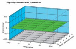
Today’s state-of-the-art compensation circuitry takes advantage of recent cost and size reductions in microprocessor technology to improve the overall result. An on-board microprocessor enables features such as mathematical modeling of static and thermally induced errors, making possible a dramatic improvement in performance over temperature and the combining of all error sources into one, easy-to-understand number called Total Error Band (TEB).
Other important features include the addition of a multi-drop digital interface, thereby eliminating the cost of analog cabling and enabling more economical network configurations. Additionally, the readout of transmitter temperature and even re-ranging the analog output with different zero and full scale values are easily realized. Finally, a guaranteed option that insures against damage due to transient surges (i.e., nearby lightning strikes) is essential to installations in certain parts of the country. Just make sure your transmitter supplier guarantees the result.
Packaging
Recent advances in mechanical packaging serve to improve the survivability of pressure and hydrostatic level transmitters. While 316 stainless steel is a popular and relatively inexpensive choice, there are certain input media exposure to which will result in premature and catastrophic failure. In these instances, it is necessary to specify an alternate wetted material. A competent transmitter supplier should be able to recommend a suitable material for each application, providing the media to which the transmitter will be exposed can be fully defined. Connections for electrical ingress/egress are simplified for non-submersible pressure transmitters and can be either cable through a water-tight strain relief or suitable connector.
In the case of hydrostatic level transmitters, the transmitter is usually suspended into the liquid being monitored by a self-supporting cable. The outer jacket of this cable must also be compatible with the liquid. In the past, polyurethane was chosen as the general purpose jacket material, primarily because of cost. For media not compatible with polyurethane, Tefzel was usually offered at much higher cost. More recently, Hytrel is being specified as a jacket material due to its combination of low cost yet superior chemical resistance as compared to polyurethane. Polyethylene has also been found to suffice for many applications where Tefzel was once specified, again at much lower cost.
Whichever the choice of jacket material, this cable will typically be shielded and will include a small vent tube. This tube serves to vent the reference side of the pressure sensor to atmosphere, thereby cancelling inaccuracy caused by varying barometric pressure on the surface of the liquid. The proper selection of the inside diameter of this vent tube is paramount to the prevention of moisture condensation inside the tube, which can ultimately lead to premature failure of the transmitter. For those designs where the vent tube diameter is not optimized, various protection techniques such as desiccant dryers and aneroid bellows are sometimes employed to combat this potential problem. As desiccant dryers require periodic maintenance, they can be impractical for remote installations. As well, aneroid bellows can introduce errors that are unacceptable in high-accuracy applications.
So what to do when faced with making a high accuracy level measurement in a remote location where high humidity is common?
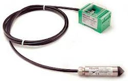
The answer is sometimes referred to as “AA” technology, as acronym for “absolute-absolute.” This technique uses two absolute transmitters to eliminate the vent tube problem completely. The first is a submersible level transmitter with unvented cable, which measures the hydrostatic pressure created by the water column plus barometric pressure acting on the surface of the water. The second is an above-ground transmitter which measures only the barometric pressure, which is then subtracted from the submersible output to yield the level measurement.
In most cases, the user is forced to purchase two transmitters and perform the subtraction externally, which can be cost- prohibitive, cumbersome and difficult to maintain. The most elegant solution uses a “system” approach, wherein the barometric offset is seamlessly and automatically removed from the output of the submersible transmitter, yielding a corrected output without the need for any external overhead. Other advantages to this approach can be separate digital outputs for both level and barometric pressure as well as water temperature. While more costly than a conventional, “vented” level transmitter, this technique can make possible high-accuracy measurements in remote, hostile environments where all other techniques will fail.
Bottom Line
The user or specifier must insure that the media is well understood so that appropriate materials of construction can specified. A transmitter with flush-welded sensing diaphragm and optional material choices for hostile media is best. Secondly, the “error budget” must be understood and a transmitter specified that will accommodate this budget over the entire range of operating temperature. A transmitter with performance specified in terms of Total Error Band provides the best solution.
Finally, in submersible applications, a cable jacket material that offers the best combination of chemical resistance versus cost should be chosen. Except in extreme cases, Hytrel or polyethylene are good choices. Where concerns of moisture entering the transmitter through the vent tube are justified, especially in remote installations, transmitter suppliers should be able to provide an “AA” solution that is easy to install, configure and maintain.
About the Author:
Mark Miller is General Manager of Keller America Inc, the North American subsidiary of Keller AG für druckmesstechnik. Keller AG is one of the world’s premier developers and manufacturers of piezoresistive-based pressure and level sensors and transmitters.
