Computer Simulation Helps Prevent Nitrification of Storage Reservoir
Computer simulation played a key role in reducing the potential of nitrification occurring in a water system that is converting from chlorine to chloramine disinfection. In moving to chloramines, it’s very critical to avoid dead spots in storage reservoirs where the new disinfectant might break down into nitrites and nitrates. These compounds would encourage the growth of bacteria.
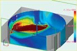
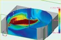
The City of Brisbane, CA, which is moving to chloramines, proactively decided to head off problems by simulating the movement of water through its storage reservoirs using computational fluid dynamics (CFD). The simulation revealed that the original single-inlet design created a large eddy between the center column and opposing tank wall that resulted in regions of poorly mixed water.
Further iterations showed that the dead spots could be eliminated by installing a manifold mixing system with multiple inlets. Each new manifold distributes the system’s available momentum flux instantaneously across a larger region of each reservoir. After manifold installation, measurement of free chlorine residuals showed that the dead spots had been minimized.
The use of chlorine and chlorine compounds is by far the most common disinfection method in the United States. The downside of chlorine treatment is that disinfection byproducts (DBPs), including trihalomethanes and haloacetic acids, are formed when chlorine reacts with naturally occurring organic matter (NOM) in the source water. Human epidemiological studies have suggested a weak association between certain cancers and reproductive and developmental defects and exposure to chlorinated surface water. More than 200 million people in the United States consume water that has been disinfected with chlorine so health risks associated with disinfection byproducts need to be taken seriously even though they are very small.
The Safe Water Drinking Act has established a series of benchmarks that call for water supply utilities to progressively reduce the maximum residual values for trihalomethanes and other DBPs. To comply, many water supply systems are preparing to convert to alternative disinfectants, such as chloramines, that do not react with NOM to form DBPs or form minimal amounts of DBPs. New regulations also require detectable disinfectant residual levels or very low bacterial levels, measured as plate counts, in water distribution systems.
Chloramines are also more persistent in distribution systems because they break down much more slowly than free chlorine.
Water circulation concerns
Water storage reservoir circulation has not been a major concern in the past because chlorine is forgiving of circulation problems and no regulatory restrictions existed for disinfectant residuals in distribution systems. Chloramines, on the other hand, break down through a nitrification process that can provide nutrients for bacteria if they are allowed to remain in dead spots. For this reason, utilities moving to chloramine disinfectants face the challenge of evaluating and in many cases improving circulation within their water storage reservoirs.
The City of Brisbane faced a tight schedule to prepare its water system for operation with chloramines. It used a design/build bid to speed the process. The city awarded the contract for upgrade of four existing reservoirs to Spiess Construction of Santa Maria, CA, teamed with INCA Engineers and Brown and Caldwell. The first task was to evaluate the circulation within the tanks. In the past, the only method engineers had to evaluate reservoir circulation was to build a scale model and perform experiments. This approach is expensive and time-consuming and, worst of all, may provide inaccurate results in many cases because of scaling factors and a very small number of point measurements.
For these reasons, Spiess Construction hired INCA Engineers to perform CFD on the existing tank configuration as well as alternatives. The tanks used by the municipality range from 33 to 92 feet in diameter and hold from 200,000 to over 1,000,000 gallons. Their purpose is to provide storage reserves to handle peak demands, supply disruptions and fire demands.
The original tank designs used a single pipe that penetrated the floor or shell of the tank. Positive head was applied to this pipe to fill the tank and negative head was used to drain it.
A CFD analysis provides fluid velocity, pressure and solute concentration values throughout the solution domain for problems with complex geometries and boundary conditions. As part of the analysis, a researcher may change the geometry of the system or the boundary conditions such as inlet velocity, flow rate, etc. and view the effect on fluid flow patterns or concentration distributions. CFD also can provide detailed parametric studies that can significantly reduce the amount of experimentation necessary to develop new or modified equipment.
Performing CFD analysis
INCA Engineers selected Flow-3D® CFD software from Flow Science Inc., Santa Fe, NM, because the developers deliver continual improvements that increase modeling accuracy and reduce the time required for modeling. One example that played a role in this project is the nested mesh concept that makes it possible to mesh small areas of the model in very fine detail while allowing larger areas to remain coarse in order to keep solution times short. This capability played an important role in modeling nozzles as small as two inches in diameter without loss of accuracy.
INCA Engineers began by drawing the tank details, such as nozzles, in AutoCAD computer aided design software, exporting a surface model in STL format, and importing the STL file into Flow-3D. The CFD software made it possible to set the nozzles into the correct position in the tank and study the effectiveness of the resulting design in a five- to 20-minute filling cycle.
Text output data, available from Flow-3D results files, were used for existing and projected condition simulations. Data for three different time intervals during each simulation condition was obtained. The text file contained the disinfectant concentration in each fluid cell at each time interval for the particular tank condition. A statistical program developed by INCA was used to compute a disinfectant concentration cumulative frequency curve for each set of results.
The cumulative frequency curve was constructed by comparing each computed disinfectant value to a specified set of disinfectant values that cover the range of possible values; then assigning each computed value to a “bin” for which the number of values assigned are counted. The count is converted to a fraction of the total values, and the fractions are summed in order of increasing bin values. The result is plotted as the disinfectant concentration versus percent of water in the tank that is less than or equal to the indicated value.
Simulation results
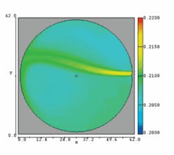
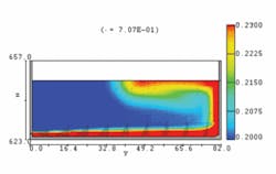
The simulation results of the original configuration showed that for the initial tank, the single-inlet generated a bottom jet that spreads and rises upon intersecting the opposing tank wall. This circulation pattern leaves a region in the center of the tank that receives less mixing than at the bottom and surface of the reservoir.
Brown and Caldwell developed conceptual plans for simple mixing manifolds, based on designs it had applied successfully elsewhere. A manifold system was used to introduce water near the center and to the far side of each reservoir. The manifold configuration has a cluster of smaller inlet valves located in the center third of the tank diameter and two larger inlet valves located near the far tank wall. The outlet valves are located near where the pipe penetrates the tank.
Check valves supplied by the Red Valve Co. are used in each inlet. The valves’ opening is proportional to the inlet pressure, maintaining a more-constant inlet velocity in order to maintain higher jet velocities at lower flow rates. The multiple turbulent jet directions developed by this manifold entrain a larger ambient water region and provide complex mixing patterns.
The simulation of the new manifold showed dramatic improvement in mixing efficiency. The results indicate that nearly the entire tank is being mixed by the system at the end of a 25-minute simulation interval. The statistical program also showed substantial improvements in disinfectant distribution. While the original simulation showed that 80% of the tank had a disinfectant concentration of 0.20 milligrams per liter (mg/L) or less, only 20% of the tank had this low a concentration with the standard Brown & Caldwell mixing manifold. INCA Engineers evaluated a number of different manifold configurations, using different numbers and sizes of inlet valves and putting them in different positions.
While they were able to make further improvements by tweaking the design, the standard manifold design provided sufficient mixing efficiency at a lower cost, so the decision was made to use it.
Spiess Construction installed the new manifolds in the four tanks before the switch to chloramines. This allowed each system to be tested in advance to insure they provided sufficient mixing efficiency. The tests demonstrated that disinfectant was consistently maintained at levels above 0.25 mg/L at all levels of the tank, indicating excellent mixing and the elimination of dead spots.
Acknowledgements
Barry Matchett, Tank Division Manager for Spiess Construction, was instrumental in coordinating the CFD simulation study during the design phase of the project. For more information on the modeling system, visit the Flow Science website at www.flow3d.com.
About the Authors:
James Dexter, formerly with INCA Engineers, is currently a Hydraulic Engineer with JD Hydraulic Engineers in Sammamish, WA. His 34 years of civil engineering experience includes hydrologic and hydraulic modeling of many types of civil engineering projects. William Faisst is Vice President, Brown and Caldwell, Walnut Creek, CA. Dr. Faisst has worked for Brown and Caldwell since 1976 on a variety of environmental engineering assignments for the planning, permitting, design, construction, and operation of water and wastewater facilities. Michael Duer joined Red Valve Company in 1994 and is currently the Senior Design Engineer of the Tideflex® Check Valve product line. He has been involved in design and applications engineering for 11 years, specializing in control and check valves. Jerry Flanagan is an Assistant Engineer with the Public Works Department of Brisbane. He presently manages the Capital Improvement Projects for the City of Brisbane and Guadalupe Valley Municipal Improvement District Water Distribution Systems and is responsible for the planning, operation, maintenance and monitoring of the two water districts supplying potable water to the city.


