Modeling Software Demonstrates Tank's Ability To Survive Earthquake
By Jack Thornton
In the hills south of San Francisco sits a million-gallon steel water storage tank that provides the local domestic water supply. Beneath it, buried in the hills, lies the infamous San Andreas Fault, building up stress for a major seismic event. Below the hills and the tank lies a stress of a different kind - lack of housing - which is building just as quickly in the overheated California real estate market. This is some of the Bay Area's most desirable remaining land for housing. To a subdivision developer, the real estate downhill from the water tank is very valuable.
The potential for tank failure during some foreseeable earthquake - what Californians call The Big One - is a considerable risk to the development, and to estimate the degree of risk and the potential consequence from tank failure was not an easy task. With public opinion against the development, one of San Francisco's leading structural engineering and earthquake specialist firms, URS/Dames & Moore, was called in.
Led by Ahmed Nisar in San Francisco, the engineering team considered how best to tackle the project of determining earthquake risk, and what resources would be required.
"Our main focus was to demonstrate to the public that the tank will not fail, resulting in a wall of water coming down the hill in some kind of an Armageddon scenario," said Nisar. "Seismic response of steel water tanks is very complex. And since this tank is not anchored to the foundation it can shift or lift off the foundation."
From an analysis standpoint, this is a difficult problem to solve because of a high degree of nonlinearity in tank response. Most simplified analysis techniques had already shown that the tank was likely to fail. But how? That was the question. If the failure mechanism could be predicted, the real estate developer was prepared to formulate a mitigation scheme to divert the water away from any development.
Paul Summers and Paul Jacob, the URS/Dames & Moore analysis team, entrusted their calculations and analysis to a software system distributed by Ansys Inc., Canonsburg, PA. The underlying product, LS-DYNA, was developed by Livermore Software Technology Corp., Livermore, CA. Originally conceived by its author, John Hallquist, at the Lawrence Livermore National Laboratories (LLNL) to simulate high-energy phenomena, LS-DYNA has received more than 20 years of continual development and enhancement for the purposes of simulating complex nonlinear problems.
The core of the system is an explicit time integration scheme that allows it to cater to the nonlinear transient dynamic response problems typified by events such as vehicle crash-worthiness, blast effects and explosions as well as the complexities of material forming.
"LS-DYNA was chosen over other analysis codes for its ability to model the nonlinearities and rapid changes in applied forces to the tank," Jacob said. "In an earthquake, the unanchored tank could lift off the slab, move and come down with considerable impact, generating considerable contact forces as well as material nonlinearity."
Since the explicit solution does not need to search for equilibrium at each time step, it could reasonably be expected to cope with this type of problem.
"LS-DYNA would need to use small time steps, to ensure solution stability, but this was not expected to be a difficulty. We required proper modeling of the earthquake's energy input to the structure anyway," Nisar said. "This meant that a small time step, on the order of at most 0.01 second, would be needed to define loading conditions."
The problem presented to URS/Dames & Moore was what could happen when 1.5 million gallons of water, weighing 7,100 tons, contained in 20 tons of 30-year-old steel, is violently shaken in an earthquake. The final results showed that the tank could withstand the anticipated level of earthquake shaking used in studying a number of similar events. The earthquake event considered was evaluated using a probabilistic approach that included fault slip rates and historic earthquake data to develop synthetic earthquake time histories.
"It was important for us to capture the 'fling' effect of the fault, which is caused when the ground rupture moves at lightening speed along the length of the fault," said Nisar.
To make sure of actual conditions, Summers made a trip to San Francisco from the URS/Dames & Moore Houston office, where he and Jacob work, to meet with Nisar and see the tank first hand. The tank is 75 feet in diameter and 53 feet high.
"It sits unanchored on a four-foot-thick ring of concrete," Summers said, "but we could not start until we knew if the slab was cracked in any way and under what conditions it might fail. The slab was sound and there was no erosion around it."
Nor were there any leaks in the shell, which could indicate a weakness in the steel, he added.
"The tank sits in a hostile environment. Being so close to the Pacific Ocean, the moisture laden air is particularly corrosive," Nisar said. "We, therefore, hired a material testing specialist to inspect the quality and workmanship of the welds. He gave us the green light."
This was good news to Jacob.
"If there were cracks in the slab or defects in the tank we would have had a far bigger problem to solve," he said. "We would have had to model the slab, the ground beneath it, and the weldments. As it turned out, we only had to model the main steelwork of the tank (shell courses, bottom plate and roof) and the water inside. We could also treat the concrete slab as a rigid surface and apply the earthquake motion directly to the tank base in the form of acceleration time histories."
The biggest modeling challenge was, of course, how to represent the tank's contents, the water.
"Backed by studies from the American Water Works Association (AWWA) and other industry standards organizations, we decided to 'idealize' the water rather than actually model it." Jacob said. "Modeling would have added at least an order of magnitude to the solution time."
"The movement of water in a shaken tank is two-phased, convective or sloshing in the upper part of the tank and impulsive below," Summers said. "The wave action of the water occurs only at the top, whereas the water down below moves in unison with the tank shell."
The AWWA standards for evaluating the ratio of the two water components, and the heights at which they act, were used as a reasonable approximation for this analysis.
Sloshing of the water was idealized as a spring-mass system as a series of radial springs attached to the tank's inside surface at the correct height of the convective mass. Modeling the steel tank followed. The steel was late 1960s vintage A36, widely used in tanks then and now.
"Its main properties - yield strength under stress and ultimate strain - were known with reasonable confidence," Jacob said. " But because of its age, its modulus of elasticity and post yield data could only be estimated."
Since evaluating a credible upper bound on risk was the object of the analysis, Jacob and Summers used a worst case, that the metal was perfectly plastic.
"That meant that all potential energy absorption due to work hardening would not be taken into account," Jacob explained. "Further, we could not quantify with any degree of confidence the damping in the system (which might reduce the earthquake effects), so again we conservatively ignored it."
These effects could be added later if necessary once the simulation was 'debugged' and considered to be behaving in a realistic way. The team did want a second set of data for comparative purposes. As a rule, one set of analysis data is insufficient for making the trend in response. To get a second set of data the engineers also used the comparison of including work hardening.
The tank's base steel was one-quarter inch thick. Shell courses were three-quarters of an inch at the base and 11/16-inch near the roof. The analysis mesh for the tank were 6x6 inches in the lower shell course and 6-inch radially by 8-inch circumferentially in the tank's bottom plate.
"The team also took advantage of a single plane of geometric and loading symmetry in the structure," said Jacob. "This allowed us to determine response from a half model."
The resulting model had 4,218 nodes, 4,255 elements (4,156 shell elements and 99 beam elements) and 25,308 degrees of freedom.
Next to be accounted for were the loads on the structure. Hydrostatic pressure was applied first.
"This is a static load that would definitely influence dynamic response of the tank," Jacob said. "With the tank full of water (14,200,000 pounds), this was the significant part of vertical loads due to gravity on the structure."
Hydrostatic pressures were applied as a linearly varying pressure distribution and a constant distribution on the inside of the tank shells and tank base, respectively. Earthquake loads then were applied to nodes on the tank base as acceleration time histories in the horizontal and vertical directions.
"Not a huge model but it added up to a respectable 500 megabyte (MB) solution database," said Jacob.
Running each analysis took about 15 hours on the workstation available, a 6-year-old Silicon Graphics Inc. PowerIndigo containing SGI's R8000 CPU with a clock speed of only 75 MHz. By today's standards this is not a powerful machine but it was sufficient to do the job.
"The solution required evaluation of the tank response to a 15 second earthquake time history with a stable model time step of 0.03 milliseconds," Jacob said. "There were 500,000 analysis cycles. One hundred state plots were extracted every 0.15 second. Nodal history data was extracted every millisecond. Elemental history data was extracted every 30 milliseconds."
As it turned out, the 15 CPU hours per simulation was a useful buffer. "We could schedule our runs so that the daytime was spent understanding results, planning any modifications and fine tuning," Jacob said. "This left the computing to be carried out overnight.
"This also meant that the daytime hours were most usefully spent on project work. We were not distracted by other things or other projects while we waited for simulations to finish."
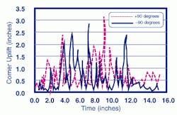
The findings satisfied Nisar's, Jacob's and Summers' engineering intuitions. At the height of the earthquake, the tank would bounce ("uplift") 2 1/2 to 3 inches.
"These were encouraging results," Nisar said, "but we took an additional precautionary step. We discussed our results with Professor George Housner, a professor emiritus at the California Institute of Technology. He told us that during his years of chasing earthquakes and steel tanks, he had noted similar levels of uplift for this tank configuration."
Examination of analysis results indicated about 9% plastic strain in the base plate at the end of the earthquake event.
Clearly, bottom plate bending is the critical factor in the tank's earthquake safety and the predominant phenomenon in the analysis. The repeated uplift phenomenon led URS/Dames & Moore to perform a simplified low-cycle fatigue assessment on the bottom plate using the Coffin-Manson Law.
"The response of the base plate was characterized by high-strain / low-cycle fatigue, where there is permanent deformation," Jacob said. "But 9% plastic strain is comfortably within the bounds of expected material plastic strain limits."
Summers added, "In our experience the most common failure mode of the tank is the buckling of the bottom part of the tank shell in the shape of an elephant's foot."
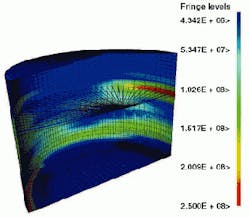
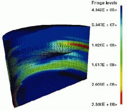
The LS-DYNA model clearly showed the bulge at the lower portion of the tank shell as the tank's bouncing up and crashing down. Sufficient forces were generated to plastically deform the steel shell. The elephant-foot outward buckling was observed at the bottom of the tank shell, just above its joint with the base plate. There was also a compensating upward bend in the bottom plate adjacent to the elephant's foot. In addition, there were convex and concave deformations at the top of the tank walls due to the convective sloshing.
Because the earthquake motion was synthetic, the team also chose to run a historical record for comparison. These two motions with the two material characteristics gave four runs for comparison purpose.
"This gave us a matrix of four cases and thus the runs would yield enough data for making a sound judgment," Jacob pointed out. "From this data, we were able to conclude that the model gave us a very good approximation of the real world."
About the Author: Jack Thornton is a principal at Mindfeed.Com, a marketing communications and consulting company.

