High Flow Bypassing Of Water Quality Facilities
By James H. Lenhart
Over the past few years there has been a proliferation of water quality treatment facilities ranging from ponds and swales to structural devices such as water quality manholes, sand filters, and vertical media filters. It has been problematic with all of these facilities that high energy flows in excess of design flows can re-suspend sediments deposited from previous storms and entrain accumulated floating oils and debris. This can cause a concentrated pulse of pollutants to flow into downstream waterways.
To minimize the occurrence of pulsing, high flow bypasses are typically installed upstream of the water quality facility. The purpose of the high flow bypass is to shunt high flows resulting from extreme events around the facility to avoid re-suspension of sediment and increase the overall effectiveness of pollutant removal.
A number of different methods are used to facilitate high flow bypassing. A common method used is to place two outlet pipes in a manhole. The smaller diameter pipe is placed at a low elevation to direct the low flows (or water quality flows) to a water quality facility. This pipe is modeled as a long tube orifice to calculate the head required to drive the water quality design flow through it. Once the head requirement is known, the invert of the larger high flow pipe is placed at the design water surface elevation.
Though inexpensive, this type of configuration does not function as well as intended. Based on field observations some of the issues encountered are:
- If the small pipe is in line with the larger pipe, shooting flows will greatly increase the flows through the small pipe and hydraulic control is lost.
- If the smaller pipe is restricted with an orifice, clogging with debris may occur.
- Since both pipes act as an orifice, during high flow events flows to the water quality facility will exceed design values.
- What is actually constructed in the field is not always what the engineer designed and the unit does not function as intended. This type of design is not field adjustable to allow for "tuning" the system in the field to compensate for construction error.
- Many times the hydraulic design of the system is complicated and incorrectly modeled e.g. using Manning's equation rather than orifice equations or culvert hydraulics to calculate flows in a short pipe resulting in improper operation.
A more sophisticated method of designing a high flow bypass uses a weir and orifice in combination. The invert of the orifice is set to the invert elevation of the inlet pipe. As flow increases the orifice will begin to submerge and build head until the flow reaches the water quality design value.
The invert of the overflow weir is then set to this design water surface elevation so that when the flow increases above the water quality design value, excess water begins to spill over the weir into an overflow pipe. Figure 1 is an example stage discharge characteristic of a system with a 3-foot weir and 6 inch orifice. The invert of the weir is set at 1.0 foot and in this example overflow begins at about 1.1 cfs.
Note the flat characteristic of the orifice vs. the exponential characteristic of the weir. The combination of these characteristics is desirable since at higher stages the flow into the water quality facility is relatively independent of the stage above the design head on the orifice. This characteristic results because the flow through an orifice is proportional to the square root head whereas the flow over a weir is proportional to the head raised to the 3
Orifice
Where Q = flow in cubic feet per second, A is the inside area of the orifice in square feet, g is the gravitational constant (32.2 ft/sec/sec) and H is the head on the orifice. C is the discharge coefficient. For a long tube orifice assume C = 0.82 (Brater and King, 1982).
Weir
Where l is the length of the weir in feet, H is the head on the weir in feet, and C is approximated at about 3.4.
Depending on the system hydraulics, other models may need to include backwater or submergence conditions. Other advantages of having a built in bypass is the water quality device is "offline" and allows for the bypassing of all flows in the event of facility maintenance or spill containment.
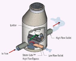
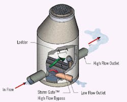
The StormGate, manufactured by Stormwater Management Inc., addresses the issues discussed above. Stormwater Management also provides engineering design and support for the StormGate and related products. More information is available from www.stormwaterinc.com.
Booth 2566


