Energy-saving RO system taps kinetic forces
By Juan Pedro Plasencia
The development of energy-saving desalination systems based on pressure exchangers has reduced energy consumption to 2 kWh/m3, which is the theoretical minimum limit for energy consump-tion for seawater applications of reverse osmosis. R.O. Kinetic of Tenerife, Canary Islands, has improved upon recent technology advances in pressure exchange-based systems by also harnessing the continuous kinetic cycle of water.
The physical principle that serves as the foundation for the system is the "incompressible property of liquids," making it possible to submit a mass of water to a given pressure without expending any energy. Pressure exchangers are used to put this principle into practice.
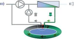
Feed water accumulated in one of the pressure exchangers is pressurised with a high pressure pump. This step is accomplished by making a closed circuit between the membrane output and the module input, where a water tank (pressure exchanger) and a booster pump are fitted into the line.
The brine output and the input to the membranes are at the same pressure, fed to them by the high pressure pump. The brine has to be fed into the pressure exchanger and displace the feed water contained in the chamber, forcing this into the module input. To achieve this, the pressure difference (_P) caused by load losses that take place in the membrane rack and in the pressure exchangers, must be overcome.
During the process, pressure falls by 1 to 2 bar at the membranes. The pressure loss that occurs in the system during the circulation of the seawater in the loops is also about 1 bar. So, the booster pump must overcome this pressure deficit of about 3 bar, in order to overcome pressure losses.
The membranes will not only be fed water from the high pressure pump, they are also fed with an amount of water that is equal to the volume of the reject, but, in this case, only the minimum energy consumption of the booster pump is required.
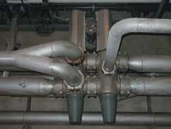
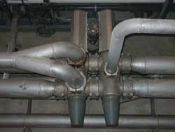
The design houses all necessary valves and other mechanisms in a very small space. It is made up of two bodies of servo-controlled valves, separated by two inertia valves. The banks of valves distribute input of seawater to, and output of brine from the pressure exchangers sequentially. The design of these valves prevents turbulence or excessive loss of load.
R.O. Kinetic pressure exchangers are in the form of a ring or closed loop, so the water entering or leaving them, which must be pressurised or depressurised, is always in continual motion to avoid unnecessary consumption of kinetic energy that arise from stops in the operation. Furthermore, they are designed so that the ratio between length and diameter reduces the chances of excessive loss of load or mixing.
The inertia valves are an extension to the pressure exchangers. The passage of the water from one chamber to another is made with practically no interruption, due to the speed with which valves are activated to maintain a continuous kinetic cycle.
Benefits
Reduced specific energy consumption. The process reaches levels of around 2.0 kWh/m3, compared with the usual average of 3.5 to 4.0 kWh/m3 in optimised facilities using "conventional" energy recovery systems.
Maximum energy efficiency. All of the reject pressure is harnessed to pressurise the sea water, without any of it being transformed into any other kind of energy, such as noise or vibrations that can end up causing breakages from fatigue in the materials of the system, or in the materials of the rest of the facility.
Smaller capacity high pressure pump. The high pressure pump only needs to manage a flow equivalent to the permeate flow, leading to cost savings in the purchase of this equipment as a less powerful pump will do the same job.
Decrease in the amount of anti-scale needed. Reducing the conversion rate to 40% compared with 45% or more in plants with conventional energy recovery systems, reduces the concentration of the brine. This leads to better flow over the membrane surface, thus reducing scaling of the membrane and, consequently reducing the quantity of anti-scale required.
Author's NoteJuan Pedro Plasencia is the sales manager of R.O. Kinetic, based in Santa Cruz de Tenerife, Canary Islands, Spain. For more information, contact by email: [email protected].


