About the author: Larry Zinser is sales engineer for Master Water Conditioning Corp. Zinser can be reached at [email protected].
A process and instrumentation diagram (P&ID), also known as a plumbing and instrumentation diagram, is a schematic of symbols that represents a complex system, such as a water treatment system. The symbols represent equipment such as filters, softeners, ultraviolet lights, storage tanks, valves, sensors and instruments. Typically, each piece of equipment and instrument on the P&ID carries a unique label. In most cases, the actual equipment and instruments at a facility also will carry a physical tag that refers to the tag symbol on the P&ID.
These symbols and sketches are useful for understanding a complex system. A P&ID provides a one-page representation of a system’s elements and their connectivity within a process. The collection of P&IDs that are drafted during a system’s initial design phase, at the installation and commissioning, during operations and maintenance, and for system modification provides a lifecycle record for the system.
What a P&ID Is
A P&ID is a schematic—a diagram of symbols that represents the system. The symbols represent the technology components in the sequence of flow, as well as flow interconnections or piping, and the locations of valves, sensors and instruments. The intent is to portray the technology components and their connectivity. The degree of detail is dependent on the purpose of the P&ID. Although the title implies a single comprehensive document, there may be a series of P&IDs for one system. Each document may represent a different aspect of the system under consideration.
When viewing a P&ID, it is essential to review the marginal information at the bottom of the page and on the legend, which normally accompanies a P&ID. The marginal information specifies the version and date of the document, the location of the system, and any document approvals. An outdated version may contain errors or lack subsequent system modifications. The legend sheet is the key to the meaning of the symbols on the P&ID. Most equipment symbols are intuitive, and most instrument symbols follow commonly accepted industry practices. However, P&ID practices can vary within the industry. The legend sheet clarifies which symbols the author used on a particular P&ID.
What a P&ID Is Not
A P&ID is not a scale or perspective drawing of a system, nor does it intend to portray how a system actually appears. It does not represent the physical positioning of equipment within a facility. A P&ID also does not identify specific items of equipment. Depending on the purpose of the P&ID, it may refer to a supplement, called the equipment and instrument list (E&IL), which provides this specific information.
Using a P&ID
A P&ID is intended to define a process. It represents the designer’s logic in the sequence of steps for a process and the components of the control strategy. Control components may include pressure, flow, conductivity, pH or hardness sensors, and sampling points for off-line testing of additional parameters. The sensors may be linked with electronic process controls that automatically monitor them and initiate alarms or internal actions based on their analyses.
A P&ID may serve as an attachment to the specification for contractors bidding for installation of the system. In this case, it may define pipe size and type, as well as valves and fittings deemed essential. An E&IL may be attached to specify the acceptable manufacturers and/or equipment models. Once the installation has been completed, the P&ID represents the installation document of record.
Once a system is installed, the P&ID becomes a reference document for routine sampling, testing and performance monitoring. System operators will use P&ID symbols to locate the specific site for collecting performance information. On some automated systems, these sensor data are automatically collected, analyzed and displayed for real-time system maintenance. If this is the case, the P&ID will describe this capability using symbols.
In a similar manner, the P&ID may be used as a reference for scheduled maintenance activities, such as cleaning or flushing sequences or operating setting adjustments. For troubleshooting or corrective maintenance, the P&ID provides the logic table for deciding the cause-and-effect nature of the system. It aids in understanding any item of equipment by noting its location within the system process. As such, the P&ID is a valuable tool for system operator training.
Lastly, the P&ID provides a record of system modifications. This is why the marginal information at the bottom of P&ID pages is important. It specifies any revisions to the document, together with approvals and approval dates. The marginal information should always be inspected before using a P&ID. An approval date that is more than three years old renders a P&ID suspect in its validity.
Evolution of a P&ID
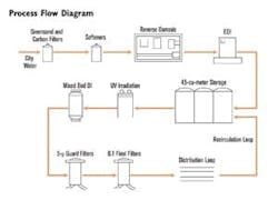
A P&ID serves as a valuable tool to document and serve the lifecycle of a water treatment system. From inception to decommissioning, it should be viewed as an evolutionary tool. In the initial idea for the system, the basic requirements for treatment are specified so that the basic technology logic and sequence can be described. This step normally is portrayed on a precursor to the P&ID called a process flow diagram (PFD), which depicts the sequence of technology required. A PFD may show a media filter, followed by a carbon filter, followed by a water softener, followed by a reverse osmosis unit, followed by a storage tank. Once the process becomes further refined, the P&ID is created with symbols and process connections. The monitoring and control strategy then is added to the P&ID, based on the operating parameters considered critical to the system. Each item on the P&ID receives a unique tag. Then, as equipment sizing begins, the separate E&IL is created to describe the acceptable specification for each tagged item.
The completed P&ID then becomes the base source document for creation of the system specification and construction bidding process. P&IDs may describe the size and material of all piping in the system. Supplemental documents such as blueprints also may be required to describe the system’s physical space, but the base remains the P&ID.
Upon installation, the P&ID becomes the base checklist for the installation qualification of the system. The equipment and valve tags enhance this inspection process. Upon system startup, the P&ID becomes the test reference for performance qualification of the system components. The performance specification is applied to the components described in the P&ID. At system commissioning, the P&ID, now the record of installation, becomes the reference for operational qualification at full production.
After installation, the P&ID serves as the reference document for routine quality control and scheduled maintenance measures. The equipment and valve tags, sensors and instruments provide continuity in performance evaluation. If performance fails established standards, the P&ID provides the structure for troubleshooting and subsequent corrective maintenance. Additionally, as requirements change, modifications to the system are recorded in subsequent versions of the P&ID. Again, the marginal information is important for confirming the most up-to-date version. Throughout the lifecycle of the water treatment system, the P&ID provides both a historical record of its evolution, and a comprehensive view of the currently approved process.
Download: Here