Quality analyzer ensures power factor correction process
New electronic power factor correction units installed at multiple motor control centers improve power quality, protect equipment and reduce costs. The Fluke 434 three-phase Power Quality Analyzer prevented potential problems during installation.
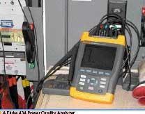
The hand-held Fluke 434 three-phase Power Quality Analyzer helped maintenance electrical specialists ensure the successful installation of new electronic power factor correction units at a regional wastewater treatment plant in the US state of Washington.
Located on the shore of the Puget Sound, the treatment facility serves six cities and processes an average of 21.1 million gallons of wastewater daily. Its daily capacity reaches up to 28.7 million gallons.
Most water treatment facilities use the same basic processes, but this one has been continuously updated since it opened in 1984, including high-intensity ultraviolet light and soon, a new Class “A” biosolids drying facility.
In this particular case, Maintenance Electrical Specialist Mark Newport was in the process of installing new electronic power factor correction units at multiple motor control centers (MCCs) to improve power quality, protect equipment and reduce costs. However, corrective measures can often introduce new power quality problems into the system, so he used a hand-held Fluke 434 three-phase Power Quality Analyzer to prevent potential problems.
The treatment plant relies on hundreds of motors, some as large as 500 hp. A SCADA control system is interfaced to the MCCs, in addition to valves, actuators, sensors, and power monitors. It also allows instant visibility into the system at numerous stations.
If the plant went down for any reason, such as a regional power outage, sewage would continue to flow through the plant and though the sedimentation tanks, but it would be discharged into Puget Sound without full treatment.
The plant electrical system features several levels of redundancy to prevent this from happening. Dual utility feeds from two substations serve the treatment facility. Generally the load is shared between the two feeds, but either feed can handle the whole facility through a tie-breaker system. A 1.25-MW generator on an automatic transfer switch can take over within eight seconds if both utility feeds fail. Small, single-phase uninterrupted power supplies (UPS) maintain the elements of the redundant control system while the generator starts and synchs.
Power correction
The power correction systems were installed primarily to correct power factor. The same conductors were used to feed both adjustable-speed motor drives (ASDs) and across the line motor starters. The ASDs are non-linear loads and draw harmonic currents, especially at the fifth harmonic. Power factor capacitors present lower impedance to higher frequencies than to the 60 Hz fundamental, so a system with harmonic currents can cause overcurrent in correction capacitors. Maintenance staff at the plant realized this and decided to use a semiconductor-based device instead.
The device they connected to each MCC continuously monitors a circuit’s power factor. It generates leading reactive power (VARs) to counteract the inductive, lagging VARs from the motors. It can respond instantly to load changes. In addition, it looks for any harmonic current and generates an inverted signal to cancel it. So, to any upstream devices it appears as if the MCC is a resistive load.
Before and after
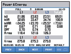
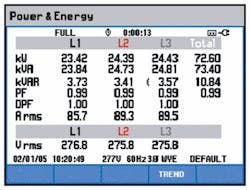
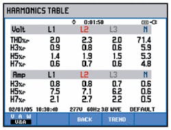
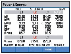
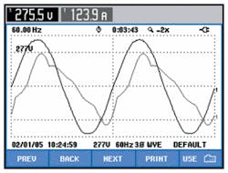
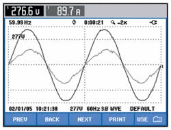
The power correction system lived up to expectations. The change in current is a real testimony to the impact of power factor correction. The rms current drawn by the MCC was reduced 27 per cent by correcting the power factor. Figures 2, 3, 5, 6, 7, and 8 illustrate the effects of the power correction system through the power measurements. The power conditioner uses a relatively small amount of power to run, but it counteracts the reactive power and reduces the apparent power (kVA) dramatically. The power relationships are illustrated in the vector diagrams (Figure 4).
Prior to the installation, the upstream distribution equipment had to carry a lot of reactive current and harmonic current that was sloshing around without doing any real work. Now the system carries only hard-working current to the MCCs.
The power corrector cleaned up the harmonic content. Most of the non-linear load was from large motor drives. The fifth harmonic was a big contributor to the overall distortion. Both the amount of the fifth harmonic current and the current THD were cut by more than 50 per cent.
Author's Note
Wade Thompson works with Fluke Power Quality, located in Everett, Washington and Santa Cruz, California, USA.
Why correct harmonics?
What is it?
Total Harmonic Distortion (THD) is the sum of the contributions of all harmonics. Harmonic distortion is a normal consequence of a power system supplying electronic loads such as computers, business machines, electronic lighting ballasts, and control systems.
What does it do?
Harmonic distortion can cause:
• High current to flow in neutral conductors.
• Motors and transformers to run hot, shortening their lives.
• Increased susceptibility to voltage sags, potentially causing spurious resets.
• Reduced efficiency of transformer - or, a larger unit is required to accommodate harmonics.
• Audible noise.
How much does an incident cost?
The major costs are associated with shortened life of motors and transformers. If the equipment is part of production systems, income may be affected as well.
Sample Calculation
Assume the cost to replace a 100 KVA transformer is $7000 including labor each year. Assume 8 hours of downtime each year with income loss of $6000 per hour.
Total Cost: $7000 + (8 x $6000) = $55,000 annually
What to check?
Motors, transformers and neutral conductors serving electronic loads.
How much is ok?
Voltage distortion (THD) should be investigated if it is over 5 % on any phase. Some current distortion (THD) is normal on any part of the system serving electronic loads. Monitor current levels and temperature at transformers to be sure that they are not overstressed. Neutral current should not exceed the capacity of the neutral conductor.
What's power factor and why does it matter?
Power factor is a measurement that compares the real power (watts) being consumed to the apparent power (Volts-Amps) of the load. A purely resistive load would have a power factor of 1.0.
What does it do?
The power available to perform work is called real power (kW). Inductive loads such as motors, transformers, and high-intensity lighting introduce reactive power (kVARs) into a power system. The system capacity is rated by the apparent power (kVA) which must be large enough to accommodate both the real power (kW) and reactive power (kVAR). Since reactive power requires system capacity, but performs no work, utilities charge more for it and plants try to keep net kVARs low. High reactive power translates to low power factor.
Power factor facts:
• Utilities may charge higher rates or penalties for low power factor or high VARs.
• System capacity restrictions cause voltage drops and overheating.
• Inductive VARs can be corrected by applying capacitors or active conditioners.
How much does poor PF cost?
Sample Calculation
Assume the utility adds 1% of demand charge for each 0.01 below PF of 0.97.
Assume your PF averages 0.86 each month and your demand charge is $7000.
(0.97-0.86) * 100% = 11%
(11% x $7000) x 12 months = $9,240 avoidable annual cost
What to check?
• See if your utility rate plan imposes a charge for reactive demand or power factor.
• Find out how the utility measures power factor or VARs. For example, are they looking at peak intervals or averages?
• Identify loads that are causing lagging reactive power and develop a strategy for power factor correction.
How much is OK?
To avoid paying higher utility fees, power factor should be higher than .97. Capacitors or conditioners may be applied on individual loads, at a confluence of several, or at the service entrance to improve power factor.
Note: This varies. Some utilities charge a rate for every percentage point between .85 and .97. Some charge a rate based on the number of VARs you use. Some don’t charge at all.


