Microtunnelling required for ocean outfall beneath coral reefs
By James Kwong, Jeffrey Kalani
Right from the start it was clear that the design of an outfall extension for the wastewater treatment plant at Fort Kamehameha, off the coast of Hawaii, would present unique challenges. The project required construction of a new 3.9-km-long ocean outfall beneath coral reefs and environmentally sensitive ocean floor. The unprecedented combination of overwater shaft construction and underwater microtunnelling were employed to complete the project.
A total of 3,900 m of pipeline will be installed throughout the project. About 2,510 m of high-density polyethylene (HDPE) pipe was installed by open trenching over a submerged shallow reef at elevations of -0.5m to -1.5m. Microtunnelling was used to install approximately 800 m of reinforced concrete pipe at seven to 10 m beneath the reef flat and sidewall of the entrance channel to Pearl Harbor. The deeper portion of the outfall is in the final phase of construction and entails installing 2,164 m of HDPE pipe at an elevation of -46 m in the Pacific Ocean off the south end of the Honolulu International Airport reef runway.
Geotechnical site characterisation included overwater drilling and sampling and marine geophysical surveys. The microtunnelling alignment that was selected avoided thick deposits (more than 50 m) of loose, liquefiable sands. Two 400-m-long microtunnel drives, one jacking shaft, and two underwater retrieval pits were constructed in open ocean waters over six metres deep, with the microtunnelling shaft bottom at 12 m below sea level.
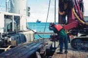
Six overwater borings explored the microtunnel portion of the alignment. The borings were drilled to elevations ranging from -10 m to -27 m, using a SIMCO drill rig mounted on a pontoon for the shallow reef flat borings. For the borings in deeper water, a large barge and truck-mounted Mobile B-53 was used.
During field exploration, wave conditions and tidal fluctuations influenced drilling progress, particularly over the shallow reef flat, where large breaking waves repeatedly interrupted drilling. Laboratory tests for microtunnelling and shaft construction included: classification and index tests, specific gravity, unconfined compression, triaxial compression, hardness, and petrographic examination.
The microtunnel alignment was selected to avert crossing through a 300-m-wide erosional channel infilled by soft silt and loose sand to more than 50 m below the ocean floor. The geotechnical analysis had indicated that the silt and sand were in a liquefied state.
Subsurface conditions along the microtunnel alignment required microtunnelling through full-faced and mixed-face conditions consisting of saturated lagoon deposits and coralline deposits, including beach sand and coral reef rock (limestone). Approximately 85% of the alignment consisted of loose silty sand and gravel, soft sandy silt, layers of hard cemented coral reef rock, and loose to dense sand and gravel with cobble- to boulder-sized coral chunks and clasts. The rest of the alignment consisted of a full face of hard coral reef.
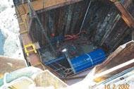
The project required the construction of a watertight microtunnel jacking shaft with a full-perimeter excavation support system and either two watertight microtunnel receiving shafts or two underwater receiving excavations. The choice was a watertight jacking shaft using interlocking steel sheet pile walls with a groundwater and seawater bottom plug created by jet grout ground improvement. Open underwater pits were excavated for retrieval of the microtunnel-boring machine (MTBM) at the end of the two microtunnelling drives.
The open ocean microtunnel jacking shaft entailed a number of design, construction, and operational challenges, including:
• The open ocean shaft needed to withstand tidal fluctuations, wave forces, and storm surges throughout shaft construction, microtunneling, and pipe connection phases.
• Poor subsurface conditions created difficulties for sheet pile driving and installation of the jet grout groundwater and seawater bottom plug. To address that issue, the geotechnical report indicated that pre-drilled continuous, overlapping holes would be needed to properly install the excavation support system.
• To prevent inflow of subsurface material and groundwater, MTBM entrance/exit seal and thrust blocks were required outside the open ocean-jacking shaft. Construction of these seals and thrust blocks required a work platform that extended beyond the limits of the shaft perimeter.
• Barges and other specialised marine vessels had to support shaft construction, jet grouting, and microtunneling operations at the open ocean jacking shaft. Logistics normally taken for granted, such as delivering cement and fresh water for jet grouting operations in addition to delivering pipe to the jacking shaft, became challenging tasks.
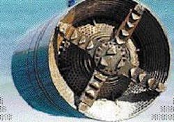
Based on subsurface conditions, microtunneling with pressurised face equipment was considered most appropriate for controlling groundwater and seawater. The geotechnical report indicated that the machine would be subjected to mixed face subsurface conditions that could cause the MTBM to ride up along the contact of the hard coral reef rock layer. Similar mixed face challenges were encountered during microtunneling where dense or cemented subsurface material was present on one side of the MTBM while loose, uncemented or soft subsurface material was present at the other.
Performance specifications for the microtunnelling equipment required that the MTBM must be capable of tunnelling through mixed face subsurface conditions and coral reef rock and cemented coral layers up to 62 MPa in unconfined compressive strength. It was also necessary that the MTBM maintain a balanced tunnel heading by applying positive pressure at the tunnel face with a recirculating slurry system to balance the soil, groundwater, and seawater pressures and prevent loss of ground. Grouting ahead and outside of the MTBM stabilised loose zones or cavities within the coral reef formation.
Microtunneling shaft construction began by dredging an access slip in the reef flat to provide access for a large crane barge. The access slip was excavated on the ocean side of the shaft so the deeper, dredged bottom would reduce the number and force of breaking waves against the shaft excavation support system. Steel pipe piles were then driven to support a work platform above the shaft area.
Pre-drilling to depths of 15 to 20 m below sea level was performed along the shaft perimeter to allow the interlocking steel sheet piles to be driven through the cemented coral reef rock layer. The sheet piles were used to create a full perimeter shaft support system and coffer dams that were installed at each end of the shaft over the entry and exit seals to contain jet grout spoils.
The pre-drilling permitted the creation of a bottom plug for stability and groundwater control using a single fluid method of jet grouting. Cement grout also was used as drilling fluid while advancing the grout rods/nozzle to jet grout column depth range of eight to 15 m below sea level. Prior to beginning each jet grout column, a form of permeation grouting filled natural voids and fractures within the coral reef structure.
The combined use of overwater shaft construction and underwater microtunneling proved effective, and construction of the two 400-m-long microtunneling drives was completed within three months.
Authors' NoteJames Kwong is vice president and Jeffrey K. Kalani is the senior geotechnical engineer of URS Corporation, Honolulu, Hawaii, USA. URS was the geotechnical and trenchless consultant on the project; SSFM International was the prime design consultant; Healy Tibbits Builders, Inc., was the general contractor.


