Sewage Disposal in Croatia’s Capital
By Dr. Reinhard Schröder
Two German companies unite to build a €350 million wastewater treatment plant in Zagreb, Croatia, that’s one of the largest environmentally sustainable projects in Europe.
In the past, the entire sewage of the city of Zagreb, Croatia – with about 800,000 inhabitants in the city and 1.1 million to 1.2 million in the catchment area – was discharged untreated into the river Sava.
In 1999, a contract was concluded between the city and the consortium WTE Wassertechnik GmbH and RWE Aqua GmbH for construction of a central wastewater treatment plant (WWTP), including the necessary infrastructure. Under WTE’s leadership, the scope of this contract was realised through a classic public-private partnership (PPP) model.
null
null
The public works comprised:
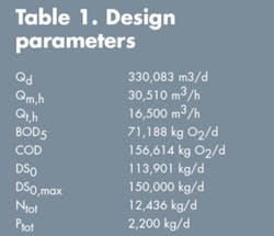
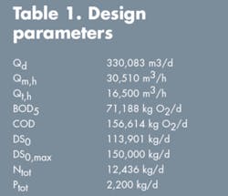
- The central WWTP for a final realisation of 1.5 m PE, i.e., a 1.5 million population equivalent, including inhabitants and industry]. In a first step, the plant was conceived for an operational capacity of 1.2 m PE. Additional design parameters are detailed in Table 1.
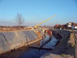
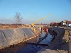
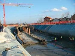
- The Main Drainage Channel (MDC) has a length of 5.5 km. It consists of two sewage collecting channels – the South Channel, completed as reinforced concrete arch pipe of 3.8x2.4m, and the North Channel, completed as glass fibre reinforced plastic (GRP) pipe DN 1400 – as well as a medium-sized box section completed in reinforced concrete 12x4m for discharge of surface water.
- A combined sewage overflow (CSO) canal.
- The southern Main Collecting Pipeline (MCP), with a length of 10.5km completed as GRP pipeline DN 1000, and the Micevac pumping station.
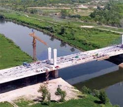
- The almost 1,000m long main bridge over the river of Sava called Domovinski most (which means “country bridge”). This bridge connects the new southern part of the town with the WWTP site on the north side of the Sava. Attached to this bridge is a sewage pipe DN 100 and a drinking water pipe of equal size as well as supply lines for gas, electricity and telecommunication.
- The sewage disposal administration centre.
- An access road to the central WWTP.
null
null
Financing & Startup
The contract value amounted to over €250 million, with a total investment of over €350 million. Project financing was realised through the German Reconstruction Loan Corp. (KfW), of Frankfurt, and European Bank for Reconstruction & Development (EBRD), in London, as well as a contribution by the consortium of about 20%.
Completed in phases, the mechanical part of the plant was put into operation in April 2004. By July 2007, over 50% of the biological stage and sludge treatment were completed and in operation. The entire plant was commissioned Sept. 26, 2007.
Contract Structure & Operation
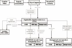
The contract structure was in the build-own-operate-transfer (BOOT) model with the WWTP’s operational structure illustrated in Figure 2.
Around the clock, the plant is run by 50 employees. Operation is guaranteed by the consortium for a period of 28 years. Besides WTE and RWE Aqua, a subsidiary of the city of Zagreb – Zagrebaèke Otpadne Vode d.o.o. (ZOV) – is involved in the operation of the plant.
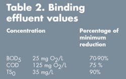
The mechanical treatment and biological carbon elimination were realised in compliance with Croatian legal requirements. Arrangements for tertiary treatment, meaning nitrate and phosphorus elimination, were made in the original design where the following parameters were considered (see Table 2).
null
Three Process Units
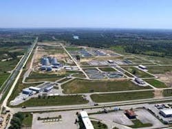
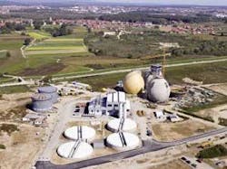
The wastewater treatment plant consists of three process units, a mechanical treatment plant, biological treatment plant and sludge treatment plant.
null
Mechanical treatment plant
The mechanical treatment plant is composed of the following plant components:
- Inlet structure
- Pumping station with eccentric screw (progressive cavity) pumps
- Screening building
- Grit chamber and grease trap
- Machine building
- Volume meter and sewage acceptance station
The flows of the MCP and the MDC are brought together directly in front of the pump sump of the screw pump station. The inlet pump station which is currently equipped with four 17m long screw pumps (Ø = 3m) lifts the raw water up to about 8m. To protect the screw pumps, a partially automatic trash rack is installed downstream.
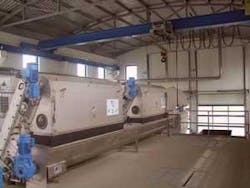
After the raw water has been lifted up, the flow is directly led through four channels to the fine screen with a screen bar spacing of 10mm. The screens are cleaned of organic solids by means of a screenings wash press. After pressing, the screenings are discharged into a 10m3 container and disposed to a landfill site.
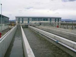
After this the raw water flows through four aerated grit and grease traps. Each grit chamber has a volume of about 1,000 m3 and a length of 50m. The corresponding grit classifier, grit container, blower and a sewage acceptance station are located in a separate building.
All plant components are enclosed or roofed with fibre glass plastic structures. The exhaust air is treated in a biofilter. The entire volume of inflowing raw water is measured by an inductive flow meter 2 x DN 1600 in a separate shaft structure (between the grit traps and primary settlement tank.
Biological treatment plant
The biological stage for the carbon elimination consists of three primary settlement tanks with a diameter of 50m each, eight aeration tanks with a volume of 6,300 m3 each, equipped with fine bubble aeration, a blower installation with three turbo blowers, 12 secondary settlement tank with a diameter of 50m each, one flood pumping station with four flood water pumps with a capacity of 12,600 m3/h each and a return and excess sludge pumping station.
Sludge processing
The sludge treatment is composed of primary sludge thickeners with a volume of over 2,000 m3 at a diameter of 24m, mechanical excess sludge thickeners (strainer beds) where the total solids are increased from below 1% to about 6.5 %, digesters with a capacity of 8,840 m3 each, digested sludge thickeners with a volume of over 2,000 m3 at a diameter of 24m, and digested sludge dewatering centrifuges downstream.
The dewatered sludge with total solids of 30% is sanitised by addition of lime and temporarily stored. Digester gas produced in the digesters is received in two gas storages containing about 3,500 m3 and continuously fed to the combined heat and power (CHP) unit, composed of two modules with wattage of 1,250 kW.
Main Drainage Channel
Formerly, the MDC – or glavni odvodni kanal (GOK) in Croatian – was an open trapezoidal channel in which the untreated sewage of the northern parts of Zagreb flowed into the Sava. This open channel flew through industrial areas as well as residential areas.
Now, a stormwater overflow structure separates the sewage from the rainwater and the sewage is conveyed to the wastewater treatment plant through closed channels. The rain and stream water flows in a closed box section towards the river Sava.
null
Combined Sewage Overflow
The stormwater discharge channel in the upper part of the MDC has an overall size of 45x26m. The structure has been designed with a parabolic overflow weir with a length of over 60m. The most favourable shape was jointly developed by WTE engineers in cooperation with the University of Zagreb.
Main Collecting Pipeline
With the southern collection pipeline, the so-called MCP, the sewage of “New Zagreb”, the part of the city located south of the Sava is conveyed to the main WWTP. In the past, this sewage entered the Sava untreated. The MCP is mainly a GRP pipe DN 1400 together with a main pumping station.
A Country Bridge
The Domovinski most – country bridge – over the Sava forms the connecting passage from the southern part of the city to the northern part and was built instead of an inverted siphon. The road is to be used not only for sewage transport but as a public transport link from the airport for direct access to Zagreb’s city centre. The suspension bridge is 990m long, 120m of which were built with incremental launching construction and pre-tensioned concrete construction in the foreland basin. It includes four lanes for car traffic, two lanes for tram traffic and a pedestrian crossing on both sides. The width of the bridge is 35m. The height of the pylons is 16m, rather low as the airport is nearby.
The administration facilities consist of an office and conference wing, storage capacities and a restaurant. They’ve been used since startup of mechanical treatment in 2004. The restaurant, which is also accessible for the public, is heavily visited. The access road to the WWTP was necessary to provide for access to the western industrial area of Zagreb to the motorway ring.
The municipality had to purchase almost 3,000 private properties for the overall realisation of the project. Beside management projects in Germany, Austria, Slovenia and Moscow, the project ranks among the largest environmental protection projects of Europe.
Author’s Note:
Having retired this spring, Dr. Reinhard Schröder is the former CEO of WTE Wassertechnik GmbH, an affiliate company of EVN A.G. that’s based in Essen, Germany. It designs, constructs, finances and operates water supply and wastewater disposal systems on the national and international market. Contact: +49 (0) 201 8968-500 or www.wte.de
