Centrifugal pumps are used in a variety of applications, from processing plants to building HVAC to the water and wastewater industries. Many of these pumps run up to full speed and either cycle on and off or just run at full speed all the time. In many instances, the pump could run at less than full speed and achieve the job needed; if it cycles on and off it is producing more than is needed to keep up. This article will explore how energy can be saved by controlling the speed of the pump with a variable frequency drive based on the pump and fan affinity laws.
For centrifugal pumps, the affinity laws show how the change in speed (rpm) of the pump or a change in impeller diameter can influence the volume capacity, head pressure, and power consumption of that pump or fan. There are two sets of affinity laws for pumps; one for a specific centrifugal pump and one for a family of centrifugal pumps that are geometrically similar. In this piece, we will be focusing on a specific centrifugal pump and on how the affinity laws effect what can be done with that pump to save energy.
Affinity Laws for a Specific Centrifugal Pump
For a centrifugal pump the power consumption is P1/P2 = (n1/n2)3(d1/d2), where P = Power, n = wheel velocity in rpm, and d = wheel diameter in feet.
For the purpose of this article, the wheel diameter is remaining constant because we are focusing on how changing the speed of the pump can save energy, so for this the equation becomes P1/P2 = (n1/n2)3.
With this equation, the power consumption is seen as a percentage of full speed power consumption, dependent on the cube of the speed. Thus, we can build a table of percentage of full speed power consumption by speed (shown in Table 1).
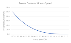
Interestingly, the power consumption of a particular pump decreases rapidly because the power consumption is based on the cube of the speed. This can be represented graphically as well as is shown in Fig. 1, though it should be noted that there is a minimum speed that a pump can effectively be operated at so this is not fully representative of what can be done in reality.
In looking more closely, it is seen that with a 20 percent reduction in the speed of the pump, the power consumption is reduced by almost 50 percent. Even a 10 percent reduction in speed reduces power consumption by 27 percent. How would we know then, how much we can reduce the speed of the pump by to be able to handle the demand needed? This is where the rest of the pump affinity laws come into play.
From the pump affinity laws, the flow rate of the pump is directly proportional to the speed of the pump, q1/q2 = (n1/n2)(d1/d2), where q = flow capacity (gpm, etc); and with the same impeller diameter this equation becomes q1/q2 = (n1/n2) and the pressure of the pump is directly proportional to the square of the speed; dp1/dp2 = (n1/n2)2 (d1/d2)2, where dp = pressure (ft, psi, etc.), and with the same impeller diameter this equation becomes dp1/dp2 = (n1/n2)2.
We have already covered that the power consumption is directly proportional to the cube of the speed, so if a pump were rated for 1,000 gpm and on average only 800 gpm were required then the pump would only need to normally run at 80 percent speed. Therefore, q1 = 1000 gpm, q2 = 800 gpm, and n1 = 100 (full speed); so n2 = n1/(q1/q2), or n2 = 100/(1000/800) = 80 percent speed, which shows that flow is directly proportional to pump speed.
For the pump which would be normally running at 80 percent speed, the power consumption would be 51 percent of the power consumption of full speed.
But what does all this mean in dollars? Adding to the example above, a 6” by 4” pump that is 20 HP can pump 1,000 gpm maximum, so let’s use that as our example. A 20 HP motor at full speed will consume 14.9 kW of power (kW = HP x 0.7457). Let’s say, on average, that this pump runs for 19 hours, pumping 19,000 gallons, per day running at full speed for those 19 hours so our power consumption would be 283 kWh per day.
Power consumption is equal to kW x time; therefore, 14.9 kW x 19 hours = 283 kWh.
For our 80 percent speed scenario, it would take 23.8 hours to pump that same 19,000 gallons, so the pump would be running continuously all the time at 80 percent speed. For this scenario the pump would be using 16 HP or 11.9 kW of power and for 24 hours we end up with a power consumption of 11.9kW x 23.8 hours = 283 kWh, but that is the same power consumed by our pump running slower. How can that be? We haven’t taken into account our pump affinity law equation yet. With that, P1/P2 = (n1/n2)3; P2 = P1 x (n2/n1)3; n1 = 80 percent speed (0.8), n2=80 percent speed (0.8); so P2 = 283 kWh (0.8/1)3 = 145 kWh.
Even though the pump would have to run continuously all day every day to pump the same number of gallons as that pump running at 100 percent for 19 hours per day, it would use 51.2 percent less power (145 kWh/283 kWh) which is the same value from Table 1 for 80 percent speed power consumption.
Note: These calculations have been simplified by assuming 100 percent efficiency for the pump, motor, and VFD, which is not a reality. Those losses would need to be accounted for in a true calculation.
Now we have seen for this example that a savings of 138 kWh would be realized on a daily basis so what does that mean in terms of dollars? If we take an average cost of 11.07 cents/kWh, which is the U.S. national average for commercial electrical rate, then that would be $31.33 for the full speed cost and $16.05 for the 80 percent speed cost — which would be a savings of $15.28 per day or $5,577.20 per year of savings just for a 20 HP pump running at 80 percent speed. If the pump ran at 70 percent speed, the savings would be $7,511.70 and if we were to look at a 100 HP pump in the same 80 percent speed scenario as above, the savings would be $27,959 per year.
As is shown here, the savings of running a pump at lower than full speed for more time can be a very significant way to save electrical costs. As the speed is reduced and as the motor gets larger, the savings continue to grow.
Two Pump Scenario
Let’s now consider a scenario where one pump isn’t enough to keep up with demand. For this example let’s say that 1,600 gpm is needed to keep up and we have two 1,000 gpm pumps. Without having speed control for the pumps, one pump would be running at 100 percent full time and the other pump would be cycling on and off, and since 600 gpm is 60 percent of the second pump’s capacity, it would run for 60 percent of the day or 14.4 hours. Combining the two, we would have a total of 24 + 14.4 = 38.4 hours of run time and the kW would be double our example above for that 38.4 hours of run time, giving us (14.9 kW x 2) x 38.4 hours = 1,144 kWh per day (rounded off). At 11.07 cents/kWh, that would be a cost of $126.64 per day to run the two pumps in this scenario.
Now if we look at these same two pumps running continuously at 80 percent speed for 24 hours per day, that would give us the 1,600 gpm needed to keep up and our kWh would be 1,144 kWh x (0.8/1)3 = 586 kWh (rounded off) and at 11.07 cents/kWh, the cost to run per day is $64.87 for a savings of $61.77 per day, or $22,546 per year of savings.
Conclusion
By running pumps at lower speeds than full speed, large savings in energy consumption can be realized. If there are situations where pumps are cycling on and off throughout the day, those are good candidates to investigate placing VFDs because they are pumping more than is needed. If the peak capacity of that pump is needed, the benefit of the VFD is that it can ramp up its speed as needed based on the process measurements being made, and most VFDs are able to do the PID control loop inside of them now, so a separate controller or PLC is not needed. WW
About the Author: Matt Backman is an outside sales engineer for Gilson Engineering Sales in Pittsburgh, Pa., and has been there since May 2011. He is a graduate of NC State University with a bachelor’s degree in aerospace engineering.
About the Author
Matt Backman
Matt Backman is an outside sales engineer for Gilson Engineering Sales in Pittsburgh PA and has been there since May of 2011. Matt is a graduate from NC State University with a Bachelors in Aerospace Engineering and has worked for Gilson Engineering Sales since graduating, working in the instrumentation and controls industry.

