Selecting the Optimum Pump Control Valve to Save Substantial Wasted Energy Dollars
By Allan R. Budris
Pumping systems account for nearly 20% of the world's electrical energy demand, and 25-50% of the energy usage in certain municipal applications. This, coupled with the fact that many pump installations are operating at much less than optimum efficiency, means that there is potential for sizable energy savings when actions are taken that can improve the overall pump system efficiency.
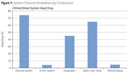
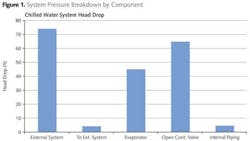
To help pump users capitalize on these system energy losses, I've dedicated many of my previous WaterWorld columns to identifying the various procedures, system components and interactions that contribute to needless wasted energy/costs. Prior topics covered have addressed energy improvements for pumps, drivers, flow control, piping, and operation, to name just a few. This column covers control valves, which are still the most common form of pump flow/pressure control. Considerable system pressure can be lost across valves, in particular control valves, in throttle-regulated installations. Figure 1 shows the substantial pressure drop impact of a fully open control valve, compared to the other major system components, for one industrial application. It should be noted that one of the reasons for the high pressure drop was that, in an effort to lower the initial cost, the valve was undersized for the piping.
CONTROL VALVE TYPES
Not all control valves are created equal with regard to pumping system pressure drop and flow control responsiveness. Gate valves are generally used for quick-opening applications, although they can and are also used as control valves due to their relatively low 100% open pressure drops. Ball valves have the lowest 100% open pressure drops (i.e., lowest "K" values), as shown in Table 1, but they do come with a higher price tag. Butterfly valves tend to have slightly higher pressure drops for full open valves. Globe valves are seldom used as control valves because of their higher cost and much higher pressure drops. These and other control valve features can be summarized as follows:
- Globe: Very responsive control but high pressure drop, over ten times the pressure drop of a gate valve at 100% open.
- Gate: Lower pressure drop but high torque at high pressure drops. Less responsive near full open.
- Ball: Lowest pressure drop when 100% open. Lower torque; quarter turn to shut off.
- Diaphragm: Sealless valve construction for corrosive, environmentally sensitive, high purity, and slurry (to 15%) applications. Elastomers limit temperatures to 100˚F to 275˚F.
- Butterfly: Medium pressure drop, compact, low cost, offered in various trims.
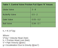
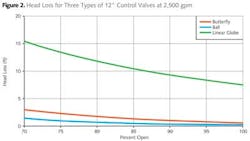
Figure 2 illustrates the pressure drop for three different types of 12-inch control valves at a flow rate of 2,500 gpm and as a function of valve opening. As can be seen, valve type can have a significant impact on the system head loss (energy costs), with the linear globe valve having the highest loss, followed by the butterfly valve, and the ball valve having the lowest value.
As stated above, the pressure drop and energy cost for a control valve can be sizable, especially for high flow rate systems, and/or high specific speed pumps.
Valve Coefficient (CV)
The pressure drop for a valve is not normally given in terms of its "K" value but instead the "CV" coefficient is normally used to convey this energy loss. The CV flow coefficient is the flow rate that will cause a 1 psid pressure drop across the valve. Thus, the lower the valve CV value, the higher the pressure drop for a given flow rate. The formula is:
| CV = Q / (dP)0.5 Where: dP = (Q / CV)2 Q = Flow Rate (gpm) dP = Pressure Drop (psi) |
The valve CV can also be determined, given the valve "K" coefficient by using the following formula:
| CV = 29.9 * D2 / K0.5 Where: D = Inside Pipe Diameter (inch) |
Control valves are often offered with different trims, which can change the 100% open CV values and the shape of the CV characteristic (CV vs. percent valve opening). Actual valve CV values can be obtained from the valve manufacturer or from field tests.
Valve Selection Issues
Once the control valve type and CV value have been determined, there are other valve issues that should be considered, some of which also impact the pump system efficiency:
- Size
- Pressure rating
- CV flow characteristics (curve shape)
- Trim
- Stem sealing
- Material
- Actuator, pneumatic, stepping motor, solenoid, geared motor, electro-hydraulic
- Control
- Intelligent positioners
Valve Energy Cost Estimates
In order to determine the true energy lost across a control valve, the efficiency of the pump (which creates the pressure) and the driver (which powers the pump) must also be considered. The formulas for the energy lost across a control valve using the valve CV coefficient then become:
| HPVALVE = Q3 / 1714 / (CV)2 / EFFP KW (IN) = 0.7457 * HP / EFFD COST ($) = $.05/KW-HR * KW * HR |
In order to use these formulas we need to make certain assumptions, such as the pump efficiency, driver efficiency, energy cost, operating hours, and the amount of control valve throttling. For an example, we have made the following assumptions (if actual values are available, these factors should be adjusted accordingly):
- Energy Cost = $.05/kW/hr
- Operating Hours = 8,760 (full time)
- Pump Efficiency = Maximum, Hydraulic Institute double suction, 1,500 Ns (see Fig. 3)
- Drive Efficiency = Standard "as-new" motor efficiency (see Fig. 3)
- Valve Opening = 50% of Maximum (full open) CV

Figure 4 shows the resulting estimated potential energy savings for a control valve throttled, double suction pump application (using the above assumed conditions). As can be seen, the potential savings are substantial, especially for lower CV values at the higher flow rates. Also, the savings will be even larger if the pump is not operating at or very close to its best efficient flow rate, which is often the case.

Corrective Actions for Reducing Control Valve Power Losses
Finally, in order to achieve all or part of the potential energy savings, the system CV must be increased by means of one or more of the following actions:
- Determine the minimum pressure drop across the control valve.
- Change the control valve type to one with a higher CV rating (if feasible).
- Change the control valve size.
- Change the control valve trim.
- Trim the pump impeller, if the maximum system requirements do not necessitate the current impeller diameter for maximum demand (a trimmed impeller would require less valve throttling).
- Change to a low flow impeller, if available.
- For high specific speed pumps (above about 4,000), consider changing to bypass flow control (see Sept. 2011 WaterWorld column on selecting the best/most efficient control method).
- Replace the control valve with a variable speed drive.

References 1. Bloch, Heinz P. and Allan R. Budris. Pump User's Handbook Life Extension, 4th Edition, Fairmont Press, Inc., 2014.