Centrifugal Pump Flow Operating Regions and Impact on Reliability
By Allan R. Budris
Ideally, a centrifugal pump should be operated at or near its best efficiency point (BEP) flow rate in order to minimize the life cycle costs. However, all centrifugal pumps have sweet spots beyond the BEP that will yield acceptable efficiency and reliability. There are limitations, though, on the minimum and maximum flow rates, beyond which the pumps should not be operated continuously (or for extended period of time), in order to avoid premature failures.
A first step in avoiding these negative low efficiency and low reliability conditions is to determine the pump BEP, preferred operating region (POR), and allowable operating region (AOR) flow rates. It is especially important to determine these flow regions because not all pump applications are static in nature or closely match the expected system demand. Because of this, pumps are often required to operate over a broad range of flow rates, which can adversely affect the pump efficiency and reliability.
A pump will always operate at the flow rate where the pump head-capacity curve intersects the system head-capacity curve. This means that it is also critical to accurately determine the true system H-Q curve (see Pump Tips, WW, January 2009), in order to establish the true operating flow rates.
Once these flow regions and the true system conditions are known, actions can be taken to maximize pump operation in the POR and avoid or minimize operation outside the AOR, thus optimizing pump life cycle costs.
BEP Flow Region
Pump performance and service life are optimized around a rate of flow designated as the BEP. At the BEP, the hydraulic efficiency is maximum, and the liquid enters the impeller vanes, casing tongue (discharge nozzle), and diffuser vanes in a shockless manner. At the BEP, flow through the impeller and diffuser vanes (if so equipped) is uniform, free of separation, and well controlled.
Lower and higher flow rates cause mismatch between the flow and the impeller and casing vanes. This mismatch causes turbulence within the impeller and casing flow passages, which both blocks the flow passages and increases the local velocities. This increase in velocity increases vaporization (cavitation) within the liquid. The greater this resulting turbulence and cavitation, the lower the pump efficiency and reliability, and the more severe the levels of vibration, noise and erosion.
POR Flow Region
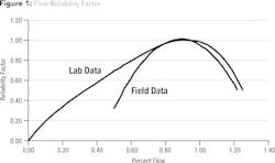
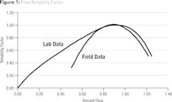
Pump flow remains well controlled within a range of flow rates around the BEP, designated as the POR. Within this region, the service life will not be significantly affected by the hydraulic loads, vibration, or flow separation. The POR for most centrifugal pumps is between 70 and 120 percent of BEP, except for high specific speed/high suction specific speed pumps that can have even smaller preferred flow regions around the BEP. Pump reliability peaks at about 90 percent of the best efficiency flow rate and falls off very quickly away from this flow rate, especially at higher flow rates (see Fig. 1).
AOR Flow Region
The AOR is the range of flow rates where the service life of a pump is not seriously compromised and is typically specified by the pump manufacturer. The service life within the AOR will be lower than within the POR. The pump energy level (suction energy and discharge energy), NPSH margin, pump specific speed, suction specific speed, and pump type all influence the specific factor(s) that establish the AOR.
By definition, a pump’s suction energy is the product of the impeller eye diameter, speed, suction specific speed and liquid specific gravity. Pumps with high suction energy and low NPSH margin ratios (below about NPSHA/NPSHR=3), especially when operated in the suction recirculation flow range, may experience noise, vibration and/or cavitation erosion damage, particularly with impeller materials that have low cavitation resistance, such as cast iron, and/or liquids that are corrosive or contain abrasive materials. High suction energy generally starts at about 3,560 rpm in end suction pumps with 6-inch and larger suction nozzles sizes, and split case pumps with 8-inch and larger suction nozzles. At 1,780 rpm, high suction energy starts with 10-inch suction nozzle size end suction pumps, and 12 inches for suction split case pumps. See Pump Tips, WW, October 2007 and December 2012 for more details on suction energy.
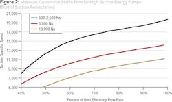
The minimum flow rate for the AOR is typically determined by the “start of suction recirculation” for high and very high suction energy pumps, especially those with low NPSH margins. The start of suction recirculation generally ranges from 40 to 100 percent of the BEP flow (see Fig. 2).
Discharge recirculation is similar to suction recirculation but occurs at the impeller/casing discharge at some reduced flow rate below the pump BEP. Although not a common problem, it can do damage to some high (discharge) energy pumps. According to the Hydraulic Institute, pumps with heads greater than 650 ft/stage that require more than 300 hp/stage, have high (discharge) energy. Ideally, the pump manufacturer will specify the minimum flow rate that will avoid operation in the discharge recirculation region for high discharge energy pumps when damage is of concern.
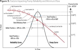
Barring a high suction or discharge energy situation, one or more of the following factors (see Fig. 3) will generally determine the pump AOR:
Temperature rise: All pumps will experience an excessive temperature rise (and possible failure) at some reduced flow rate if operated there for an extended period of time. So lacking any other destructive minimum flow factor, temperature rise will determine the pump minimum flow value. The value of this minimum flow rate is typically below about 10 percent of the BEP.
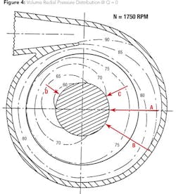
Bearing life: At flow rates above and below the BEP, the velocities and pressures around the casing volute become non-uniform (see Fig. 4), which can greatly increase the radial loads on the impeller (as discussed in Pump Tips, WW, December 2007). As a result, bearing life normally decreases as the pump flow moves away from the pump BEP (especially with single volute casing pumps). Because of this, pumps should not be operated at flow rates below or above that which will yield the minimum acceptable bearing life for the application.
Shaft fatigue failure: Non-uniform volute pressures away from the BEP can also cause cyclic loads on the shaft, which in some cases can exceed the fatigue limit. Shaft stress can be further increased by any turbulence and cavitation that is created in the casing and impeller, as discussed above. This can even be the factor that determines the pump AOR, depending on the severity of these unsteady and oscillating loads and their impact on the shaft, mechanical seal, and bearings.
Horsepower limit: Pump power draw normally limits the maximum allowable AOR flow rate. However, for high specific speed pumps above about 4,500 to 5,000, the input horsepower actually increases with low flow rates below the BEP. This HP increase can become quite excessive with very high specific speed values. Pump users will often restrict the minimum flow rate for these high specific speed pumps to reduce the pump pressure and/or required input power, and to avoid the requirement for large motors and/or stronger (thicker-walled) piping.
Conclusion
As can be seen from the above, a key factor in optimizing pump efficiency, reliability and life cycle cost is to determine the optimum pump flow range. This requires establishing the pump BEP, POR and AOR (in addition to the true system performance) in order to maximize operation in the POR and avoid any extended operation outside the AOR. The pump manufacturer should always be contacted for these values.
About the Author: Allan R. Budris, P.E., is an independent consulting engineer who specializes in training, failure analysis, troubleshooting, reliability, efficiency audits and litigation support on pumps and pumping systems. With offices in Washington, N.J., he can be contacted via e-mail at [email protected].
More WaterWorld Current Issue Articles
More WaterWorld Archives Issue Articles
