Considerations for Designing Piping Adjacent to a Centrifugal Pump

By Allan R. Budris
Many pump field problems are caused or aggravated by non-optimum piping to and/or from the pump, with poor suction piping causing many of the issues. I recall a specific field problem where the pump piping was so substandard that it caused one side of a double suction impeller to perform in low flow suction recirculation, while the other impeller inlet operated in high flow cavitation (see Figure 1). I also remember the laboratory test of a small high-suction energy pump, where a deliberate swirl was introduced to the pump suction, resulting in vibration so severe that the pump was nearly thrown from the test stand.

Accordingly, sound pump piping, especially to the inlet, is critical for optimum pump performance and life, and properly-designed suction piping determines the uniformity of the flow delivered to the pump. Inlet flow disturbances, such as swirl, sudden variations in velocity or imbalance in the distribution of velocities and pressures, can be harmful to the hydraulic performance of a pump, its mechanical behavior and its reliability. Usually the higher the suction energy and specific speed of a pump, in addition to the lower the NPSH margin, the more sensitive a pump is to suction conditions. Pump factory tests (and therefore published performance) are normally based on ample straight pipe lengths to and from the pump.
Suction Piping – Purpose
Ideally, the flow entering a pump inlet should be of a uniform velocity distribution, without rotation and stable over time. Undisturbed flow can be achieved by controlling pipe lengths and the type and location of any fittings in the suction piping system. In summary, pump inlet piping should:
- Supply an evenly-distributed flow to the pump (the ideal approach is a straight pipe)
- Have suction pipe at least as large as the pump suction
- Have maximum liquid velocity = 8 ft/sec
- Be sized to provide sufficient NPSH Margin to the pump [see "http://www.waterworld.com/content/ww/en/articles/print/volume-28/issue-12/departments/pump-tips-techniques/key-consider-help-deter-opti-npsh-margin-centri-pump-apps.html">Key Considerations to help Determine the Optimum NPSH Margin for Centrifugal Pump Applications," WW, Dec. 2012]
- Inject any pump bypass piping sufficiently upstream of the pump
Suction Piping – Hydraulic Considerations
The velocity in the suction piping should be constant or increasing as the flow approaches the pump, and the suction piping should be designed with gentle transitions if changing pipe sizes. Transitions resulting in flow deceleration at the pump inlet should not be used. Ideally, pumps should have an uninterrupted and unthrottled flow into the inlet (suction) nozzle. Velocities may be increased at the pump suction flange by means of a gradual reducer. Eccentric reducers should generally be installed with the flat side horizontal and the bottom sloped (except when the liquid enters from above the pump through a vertical elbow) to avoid the potential of forming an air pocket.
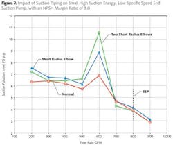
When fittings such as "T" fittings and elbows (especially two elbows at right angles) are located too close to the pump inlet, a spinning action, or "swirl," is induced. The most disturbing flow patterns to a pump are those that result from swirling liquid that has traversed several directions in various planes. This swirl could adversely affect the pump by reducing the performance and net positive suction head (NPSH) available. It could also generate noise, vibration and damage in high-suction-energy pumps. Figure 2 shows the impact (with regard to suction pressure pulsations) of three different suction pipe configurations attached directly to a pump suction flange (straight pipe, single short radius elbow and two short radius elbows at right angles). Even with a high NPSH Margin Ratio (3.0) and low specific speed, the highest pressure pulsations occurred with two short radius elbows (at right angles) on this high suction energy pump. As expected, the straight pipe inlet generated the lowest level of pressure pulsations. These elevated suction pressure pulsations are caused by cavitation, which can cause erosion damage, increased vibration, and noise.
Isolation valves, strainers and other devices used on the inlet (suction) side of the pump should be sized and located to minimize disturbance of the flow into the pump. These flow-disturbing fittings, however, should not be present for some minimum length. To achieve this, it is recommended that a straight, uninterrupted section of pipe be installed between the pump and the nearest fitting, with consideration of the Hydraulic Institute Standards for minimum straight pipe length. Elbows should be vertical when close to the inlet of a double suction pump to avoid the flow disturbances shown in Figure 1. Further, the minimum recommended suction pipe straight section lengths range from three to sixteen pipe diameters for high suction energy and/or high specific speed pumps (as shown in Figure 3). Generally, the minimum required pipe lengths for low suction energy pumps, with low specific speed, are about half of that shown for high suction energy and/or high specific speed pumps, ranging from one to eight pipe diameters.
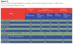
As illustrated, the recommended minimum Hydraulic Institute straight pipe length depends on the type of fitting(s), pump(s), suction energy level, and pump specific speed. Pump suction energy is the product of the impeller eye diameter, pump speed, suction specific speed, and liquid-specific gravity. Gating values for high-suction energy is governed by the pump type based on the degree of turning inherent within the pump suction passage [see "Avoiding Cavitation Damage Extends Pump Life," WW, Oct. 2007 & "Key Considerations to help Determine the Optimum NPSH Margin for Centrifugal Pump Applications," WW, Dec. 2012]. High specific speed starts above a value of 3,500, and the maximum recommended velocity in the suction piping is generally considered to be 8 ft/sec. If the minimum recommended pipe length can't be provided, a flow-straightening device should be considered.
Suction Piping – Problems
In summary, flow disturbances on the inlet side of a pump caused by poor suction piping can lead to:
- Deterioration of pump head, capacity and/or efficiency performance
- Cavitation damage to the impeller and shortened impeller life (especially with high-suction-energy pumps)
- Shortened mechanical seal life
- Shortened bearing life
- Noisy operation
- Random axial load oscillations, especially with double suction pumps
- Occasional damage from liquid separation
Discharge Piping
Generally speaking, the configuration of the discharge piping (mounted close to the discharge flange) will have little, if any, impact on the performance and/or reliability of a pump. However, there is an exception with high-discharge-energy pumps. These pumps can be sensitive to flow-disturbing fittings mounted close to the pump outlet flange. These fittings could result in increased noise, vibration and/or lower pump heads, especially near shutoff. According to the Hydraulic Institute, pumps with heads greater than 650 ft/stage that require more than 300 hp/stage have high discharge energy.
The generally-recommended minimum discharge pipe lengths for high-discharge-energy pumps depend on the type of fitting(s) downstream of the pump and the pump discharge energy level. High-discharge-energy pumps normally require 1 to 4 (and at times up to 8) pipe diameters of straight pipe after any pipe increase, with the specific minimum length dependent on the discharge energy level and fitting types. The outlet discharge pipe should normally be at least as large as the pump discharge nozzle, with a maximum velocity at any point in the outlet discharge piping of 15 ft/sec.
About the Author: Allan R. Budris, P.E., is an independent consulting engineer who specializes in training, failure analysis, troubleshooting, reliability, efficiency audits, and litigation support on pumps and pumping systems. With offices in Washington, N.J., he can be contacted via email at [email protected].
References
Heinz P. Bloch & Allan R. Budris, "Pump User's Handbook, Life Extension," Third edition, Fairmont Press, Inc., 2010.
"Rotodynamic (Centrifugal) Pumps for Pump Piping," Hydraulic Institute, 2000.